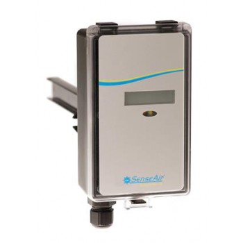





Temperature and CO2 Content Converter for Installation in Greenhouses — aSENSE GH
 Спецификация aSENSE GH
Available on request
Delivery across Russia
Order phone: +7(800)777-18-50
Description
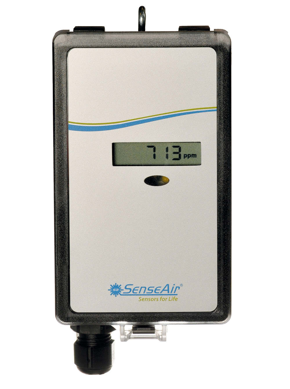
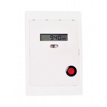
The aSENSE™-GH sensor measures both temperature and carbon dioxide content in the surrounding air, converts the obtained data into an analog or digital signal, and transmits it to the control system.
aSENSE™-GH is a fully digital, low-cost converter designed for installation in climate-controlled zones. A special coating on the printed circuit board and additional filters protecting the device from dust and moisture make aSENSE™-GH ideal for use in greenhouses, mushroom farms, incubators, and other similar applications.
Advantages
- Modern non-dispersive infrared (NDIR) CO2 measurement technology
- Maintenance-free under standard conditions
- Membrane-covered measuring chamber ensures stability, reliability, and accuracy of the carbon dioxide sensor
- Reliable and accurate built-in thermistor for temperature measurement
- Special full coating of the printed circuit board and filter make aSENSE™-GH resistant to dust and moisture
- 2 programmable output signals 0/2-10 VDC and/or 0/4-20 mA for connection to a remote central computer
- Optional RS485 digital interface for data transmission to PC and complex control systems
- Specifications
- Overall dimensions
- Connection
- Applications
|
Sensor |
aSENSE GH |
|
Measured gas |
Carbon dioxide CO2 |
|
Measured parameter |
Temperature |
|
Measured CO2 range |
0 – 2000 ppm (optionally 10000 ppm) |
|
Storage / operating temperature |
From -40 °C to 50 °C |
|
CO2 measurement accuracy |
± 30 ppm ±3% of measured value |
|
Temperature measurement accuracy |
±1 °C |
|
Dimensions |
142 mm x 84 mm x 46 mm |
|
Temperature compensation range |
From 0 to 50 °C |
|
Operating humidity range |
From 0 to 100% RH |
|
Power supply |
24 V AC/DC |
|
Response time |
1 min |
|
Data transmission |
UART (Modbus Protocol) |
|
Service life |
˃ 15 years |
|
Warranty |
5 years |
|
Output № 1 |
0/2 – 10 V DC or 0/4 – 20 mA (CO2) |
|
Output № 2 |
0 – 10 V DC or 0/4 – 20 mA (CO2) |
|
Output № 3 |
Relay output |


Jumper bars installed by default are shown in dark color
Attention!
The same grounding scheme must be used for the control system and the sensor
Connect analog outputs before starting measurement
|
Output |
Purpose |
Electrical Characteristics |
Note |
|
Terminal +
Terminal ┴ |
Power supply (+)
Power supply Ground (-) |
24 VAC/DC + (±20%), 3W
24 VAC/DC - |
2 W without output load
|
|
Out(1) CO2
|
Analog output 1 (+) 0-2000 ppm
|
0-10 VDC or 0-20mA 2-10 VDC or 4-20mA
|
According to output No.1 and default installed jumpers
|
|
Out(2) Temp |
Analog output 2 (+) 0-50°C |
Same as output No.1 |
According to output No.2 and default installed jumpers |
|
Terminal No.5
|
Relay normally closed
|
Minimum load 1mA / 5V Rated load 0.5A / 125 VAC; 1A / 24 VDC |
Standard relay on/off 1000 / 900 ppm CO2. |
|
Terminal No.6
|
Relay COM
|
||
|
Terminal No.7 |
Relay normally open
|
You may find useful
.jpg "CO2 Concentration Converter with Analog Outputs. IP 54 — eSENSE Ind advantageous low prices in St. Petersburg")