

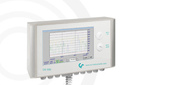


.jpeg)
Compressed air powers pneumatic cylinders and valves, participates in the operation of labeling machines, filling and capping equipment, packaging and palletizing lines, blowing and transportation systems. In practice, even small pressure losses or hidden leaks lead to increased energy consumption of the compressor room, unstable equipment operation, and higher costs.
To manage expenses, measurement is needed: monitoring current flow and accumulated consumption by lines and individual machines. This allows you to see exactly where the air is "going," how the load changes by shifts and batches, and which measures actually save costs.
Why measure compressed air flow: tasks and benefits
1. Reducing energy costs for the compressor room
Compressors consume a lot of electricity, and the air distribution system often operates "blindly." Without measurement, it is impossible to reliably:
- reduce pressure setpoints,
- optimize compressor operation schedules,
- eliminate overconsumption in specific areas,
- confirm the effect after repairs/upgrades.
2. Leak detection and network integrity control
Leaks are a typical cause of constant "background" consumption, especially noticeable at night and on weekends. Measuring flow on mains and branches reveals leaks by consumption profile: there is flow, but production is stopped.
3. Pressure drop and "bottleneck" control
Even with sufficient compressor capacity, consumers may suffer from pressure drops due to:
- clogged filters,
- bottlenecks in pipelines/fittings,
- incorrect distribution schemes,
- worn hoses and connections.
A flow meter combined with a pressure sensor helps determine exactly where the system is "choking" (high flow + increasing pressure loss).
4. Cost allocation by lines and machines
If the enterprise has several large lines (for example, 4), each feeding several machines (labelers, palletizers, filling, etc.), then the total electricity bill for the compressor room does not answer the question: who consumes how much.
Accounting by lines and key consumers allows:
- comparing lines with each other,
- seeing consumption growth over the years,
- evaluating specific consumption (per shift, per batch, per output volume),
- planning and verifying energy efficiency measures.
What exactly to measure: parameters and units
1. Current flow (m³/h, l/min, cfm)
This indicator is needed for:
- controlling equipment operating modes,
- detecting abnormal peaks (e.g., "blowing" due to incorrect settings),
- setting alarms and thresholds.
2. Accumulated flow (m³, l, ft³)
Integral consumption is needed for:
- reporting,
- cost calculation,
- period comparison (shift/day/week/month),
- cost allocation by workshops and lines.
3. Temperature (°C) and pressure (bar) if necessary
Temperature (and pressure) are important for:
- correct volume recalculation (especially when comparing different sections),
- diagnostics (overheating, non-standard compressor room modes),
- increasing data reliability during analysis.
Practical minimum for monitoring: current flow + accumulated flow.
Optimal set for engineering control: flow + temperature + pressure (on key mains).
Typical accounting scheme for 4 production lines
Below is a universal logic that is convenient to "apply" to real production.
Level 1 — accounting by mains (lines 1–4)
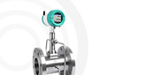
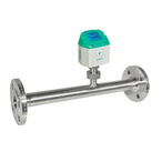
A flow meter VA 525 with a built-in pressure sensor is installed at the inlet of each line.

This provides:
- air balance by lines,
- quick identification of "who pulled" during load increase,
- basis for cost allocation.
Level 2 — accounting by key machines
Additional flow measurement sensors VA 520 are installed on branches to the most "air-consuming" consumers.

For example:
- filling/capping,
- labeling,
- packaging (carton formers, shrink wrapping, glue applicators),
- palletizers and pneumatic transport.
This allows you to see the specific consumption of each machine, identify overconsumption and leaks in a specific area.
Level 3 — leak control (night minimum)
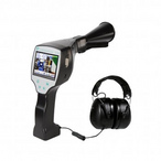
If some lines are stopped at night, but the flow does not drop to the expected minimum — this is a diagnostic indicator of leaks or incorrect modes (for example, constant purging). An ultrasonic leak detector LD 500 is used to locate leak points

How to choose a flow meter for compressed air in a pipeline (general principles)
The choice of technology depends on the tasks (accounting/diagnostics), accuracy requirements, operating conditions, installation constraints, and budget. Below is an overview of common approaches without brand affiliation.
1. Thermal mass flow meters (thermal)
Advantages:
- measure mass flow, well suited for gases,
- convenient for accounting and leak monitoring (good sensitivity at low flows),
- often have a wide measurement range.
Features:
- sensitive to contamination/condensate (air preparation and correct installation are important),
- requires compliance with recommendations for straight sections and sensor orientation.
Where applied: mains, branches to equipment, leak monitoring.
Advantages:
- technologically robust, suitable for industrial conditions,
- insensitive to contamination/condensate.
Features:
- have limitations on minimum flow (leaks "at the low end of the range" may not be detected),
- sensitive to flow profile and installation (straight sections).
Where applied: large mains with stable modes.
3. Insertion solutions for existing pipelines
If production cannot be stopped for long, solutions allowing installation through a nozzle/saddle are often chosen. This reduces the implementation time of accounting, especially on distribution networks.
Installation of a flow meter on a compressed air pipeline: engineering recommendations
Correct installation affects accuracy no less than the choice of the device.
1. Straight sections and installation location
- Follow the manufacturer's requirements for straight sections before/after the flow meter (especially after bends, tees, pressure reducing valves).
- Avoid installation immediately after elements that create strong turbulence.
2. Condensate and contamination
In real compressed air networks possible:
- droplet moisture (especially with poor drying),
- oil/aerosols,
- particles.
Recommendations:
- install devices in places with minimal risk of condensate accumulation,
- provide filtration and maintenance,
- avoid "low points" of the pipeline without drainage.
3. Valves and maintenance
Good practice for accounting units:
- shut-off valves before/after (if possible),
- bypass (if process continuity is required),
- service access availability.
Monitoring and dispatching: how to turn measurements into savings
A single flow meter without an analysis system provides limited benefit. Maximum effect appears when data is fed into dispatching/SCADA/energy management.
Interfaces and integration
Typical options you indicated:
- Modbus/RS‑485 — convenient for a network of devices on a line/in a workshop;
- Ethernet — easier for integration into IT/SCADA, remote access;
- 4–20 mA — stable for industrial automation, fast trends;
- pulse output — for simple accounting of accumulated flow.
Which screens/reports really work
For production, usually 4 levels of visualization are needed:
- Dashboard «now»: current flow by lines (m³/h), pressure, temperature.
- Daily profiles: hourly flow — shows peaks, downtimes, night minimum.
- Accumulation over period: shift/week/month — basis for KPIs.
- Alarms:
- flow above threshold during downtime,
- flow does not drop at night,
- sharp flow spike,
- flow increase with stable product output.
How to detect leaks by flow data (without complex methods)
Engineering simple and effective approach:
- Select a period when the line is guaranteed to be stopped (night/weekend).
- Look at the minimum stable flow at the line inlet.
- Compare with the expected "standby" consumption (for example, only maintaining pneumatic valves if necessary).
- If the consumption is noticeably higher — this is a candidate for leaks/blowdowns/unturned consumers.
- Next, proceed along the branches: measurement on sub-sections (or temporary portable measurements), localization, repair, re-measurement.
Important: the value is not in finding a leak once, but in making leaks a measurable metric that decreases after measures and does not rise again unnoticed.
ISO 50001 (energy efficiency) and compressed air: practical cycle
Even if you do not implement the system «formally», the logic of ISO 50001 is convenient as a engineering improvement scheme:
- Measurement — consumption by lines and key machines.
- Analysis — where consumption grows, where night consumption is, where peaks are.
- Evaluation — calculation of the effect of measures (leak repair, pressure reduction, mode optimization).
- Re-measurement — confirmation of savings and fixation of the baseline.
It is the last step that makes the savings provable: not «felt better», but better according to data.
For more information about the instruments, you can contact IZMERKON by phone +7 (812) 309 56 05 or via the feedback form.
_80x0_e6f.jpg "Pressure Transmitter Series 23SX-H2")
1)_80x0_e6f.jpg "Happy Defender of the Fatherland Day!")
_80x0_c25.jpeg "Radar Level Meter IZMERKON RL 37")


-min_146x146_c23.jpg "Стрелка")


