


LED display indicator 4...20 mA / 0...10 volts — MD 10.010 / 10.015
 Спецификация MD 10.010 / 10.015
Available on request
Delivery across Russia
Order phone: +7(800)777-18-50
Description
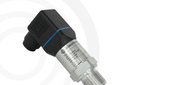
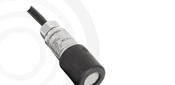
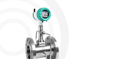
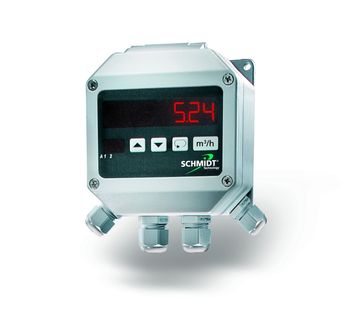
To ensure the declared metrological characteristics, the sensors must be installed in positions that comply with the operating manual requirements. Often, this leads to the built-in displays of the devices being not visible from a distance or being obstructed due to the installation location. However, there is often a need to display current values at the measurement site, next to the sensor. It is important that calculated and measured values, such as m³/h or accumulated flow, are displayed on the screen and transmitted further as an analog output signal. The LED display indicators SCHMIDT® MD 10.010 and 10.015 perfectly meet these requirements. They were designed as widescreen wall displays and can be installed in any convenient location for the operator.
Analog output signals can be connected, scaled from one (MD 10.010) or two sensors (MD 10.015) and displayed on the screen. In addition, the analog value (4 ... 20 mA or 0 ... 10 V) can be transmitted further through an analog output with galvanic isolation. Also, the measured values can be used to control two relays. Power can be supplied by mains voltage (220 V, AC) or via 24 V (DC) - connected sensors are powered directly from the display.
Control of the LED display is highly intuitive, carried out using only 3 control buttons. A small status display supports navigation in the control menu. The displayed measured values include, besides the calculated value, also the "raw" data from the sensor outputs in milliamps or volts, which greatly simplifies troubleshooting or wiring checks. Maximum and minimum measured values can be displayed by pressing one button. To protect the display from unauthorized access to settings, there is a locking option.
Advantages
- Durable plastic housing for wall mounting, IP65;
- Settings are retained even after a power failure;
- Simple and quick mounting on the wall or pipeline;
- Freely programmable for all sensors and transmitters (e.g., temperature, pressure, or humidity sensors with 4...20 mA or 0…10 V output signals);
- Adjustable averaging;
- Output of calculated measured value (e.g., volumetric flow) in calculated form on the display and as an analog signal;
- Configurable relay outputs;
- Power supply to the connected sensor.
- Specifications
- Overall dimensions drawing
- Connection diagram
- Applications
| Technical specifications MD 10.010 / MD 10.015 | |
| Display characteristics | 7-segment red LEDs, height 14.2 mm, 6 digits. Additional display: 2 digits, 7 mm |
| Input signals | 1 x 4 … 20 mA (Ri = 100 Ω) or 0 … 10 V (Ri ≥ 10 kΩ) (MD 10.010) 2 x 4 … 20 mA or 0 … 10 V (MD 10.015) |
| Analog output | 1 x 4 ... 20 mA / 2 ... 10 V or 0 ... 20 mA / 0 ... 10 V (depends on resistance, galvanically isolated, short-circuit protected) Voltage output: > 500 Ohm Current output: < 500 Ohm, 2 relays, < 250 V AC, max. 5 A |
| Analog output accuracy | ± 0.2 % of measured value |
| Power supply | 85 – 250 V AC, 50 … 60 Hz or 24 V DC ± 20 % |
| Current consumption | Max. 8 VA |
| Sensor current consumption | 24 VDC ± 15 %, max. 160 mA (short-circuit protection) |
| Operating temperature | -20 … +60 °C |
| Storage temperature | -40 … +70 °C |
| Environmental conditions | No condensation (up to 95% relative humidity) |
| Connection | 14/18 spring terminals, one conductor 1.5mm², 4 through connectors |
| Position | any |
| Protection class | IP65, contacts protected |
| Housing material | Polyamide, reinforced fiberglass (PA6-GF 15/15), color close to RAL 7001 |
| Weight | about 370 g |

MD 10.010

| Terminal | Designation | Purpose |
| 1 - 3 | Relay 1 | Relay output 1 (max. 250 VAC / 5 A) |
| 4 | Sensor 1 In- | Reference potential for analog input 1 |
| 5 | Sensor 1 In+ | Analog input 1 (jumper Ch.1 to switch between current and voltage signals) |
| 6 | Sensor 1 24V - | Operating voltage: ground (sensor 1) |
| 7 | Sensor 1 24V + | Sensor 1 power plus (24 V ± 15 %) |
| 12 | Analog Out - | Reference potential for analog output (galvanically isolated from GND) |
| 13 | Analog Out + | Analog output |
| 14-15 | Supply Voltage |
Operating voltage depending on version: DC: (14) 24V, (15) GND |
| 16-18 | Relay 2 | Relay output 2 (max. 250 VAC / 5 A) |
MD 10.015

| Terminal | Designation | Purpose |
| 1 - 3 | Relay 1 | Relay output 1 (max. 250 VAC / 5 A) |
| 4 | Sensor 1 In- | Reference potential for analog input 1 |
| 5 | Sensor 1 In+ | Analog input 1 (jumper Ch.1 to switch between current and voltage signals) |
| 6 | Sensor 1 24V- | Operating voltage: ground (sensor 1) |
| 7 | Sensor 1 24V+ | Sensor 1 power plus (24 V ± 15 %) |
| 8 | Sensor 2 In- | Reference potential for analog input 2 |
| 9 | Sensor 2 In+ | Analog input 2 (jumper Ch.2 to switch between current and voltage signals) |
| 10 | Sensor 2 24V- | Operating voltage: ground (sensor 2) |
| 11 | Sensor 2 24V+ | Sensor 2 power supply (24 V ± 15 %) |
| 12 | Analog Out- | Reference potential for analog output (galvanically isolated from GND) |
| 13 | Analog Out+ | Analog output |
| 14-15 | Supply Voltage |
Operating voltage depending on version: DC: (14) 24V, (15) GND |
| 16-18 | Relay 2 | Relay output 2 (max. 250 VAC / 5 A) |