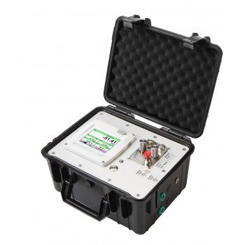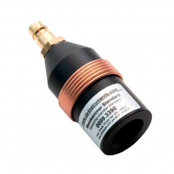
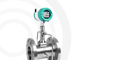
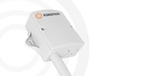
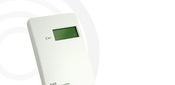
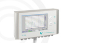



Certified dew point measurement instrument kit — DS 400 / FA 510
 Спецификация DS 400 / FA 510
Available on request
Delivery across Russia
Order phone: +7(800)777-18-50
Description
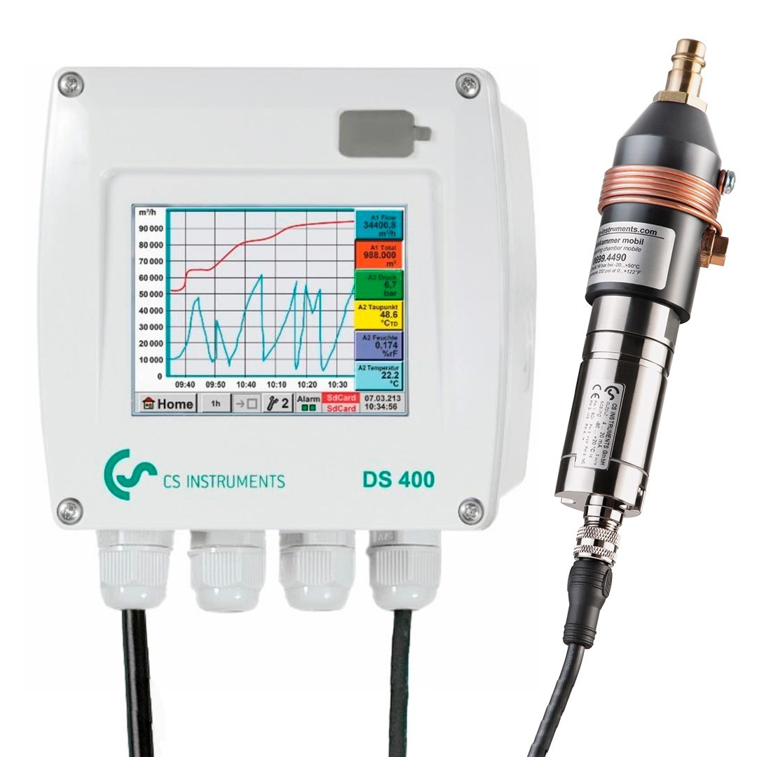
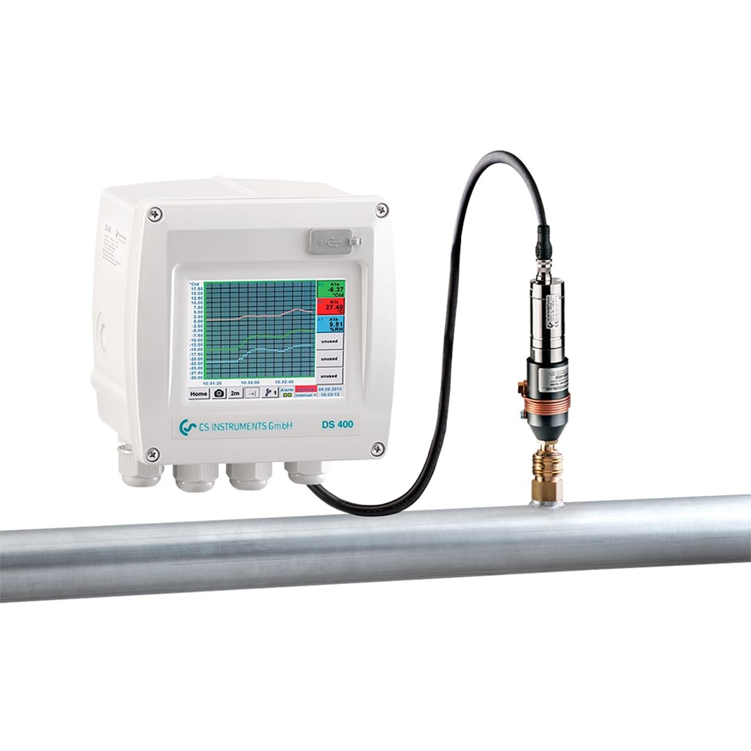
Dew point measurement kit DS 400 with FA 510 sensors for stationary monitoring of dew point temperature in refrigerated and adsorption dryers. The color touchscreen display allows quick access to measurement results and viewing of reading dynamics. 2 relays can signal when threshold values are exceeded. The device is available either with a standard analog output 4...20 mA or with a digital interface, such as Ethernet or RS 485 (Modbus). Data can be downloaded from the device via USB drive and processed in the CS Soft Basic software.
This set of instruments is registered in the state registry and has a certificate of type approval for measuring instruments.
Advantages
- Operating pressure up to 50 bar (special version up to 500 bar available)
- 3.5" color display – easy operation via touchscreen
- 2 freely configurable signal relays (230 VAC, 3 A)
- Relay activation delay adjustable for each channel
- Analog output 4...20 mA
- Option: Ethernet and RS 485 interfaces (Modbus protocol)
- Option: Web server
- Specifications
- Overall dimensions drawing
- Connection diagram
- Applications
| Technical Specifications DS 400 | |
| Enclosure Dimensions | 118 x 115 x 98 mm, IP44 |
| Connectors | 5 x PG12 for sensor and relay connection 1 x RJ 45 for Ethernet connection |
| Panel Mount Version | Panel cutout 92 x 92 x 75 mm |
| Weight | 545 g |
| Material | Plastic, front panel made of polyester |
| Sensor Inputs |
4 (2x2) freely configurable inputs for analog or pulse sensors. |
| Sensor Power Supply | Output power: 24 VDC ± 10% Output current: a) Digital input board: 120 mA during operation per channel b) Digital input board: 120 mA during operation on two channels Maximum output current on all channels: 280 mA |
| Interfaces | USB drive: USB 2.0 Ethernet TCP RS 485 Modbus RTU SDI (Serial Data Interface) other interfaces on request, option «web server» |
| Outputs | Two relays 2 (max. switching voltage: 230 VAC / 30 VDC, switching current: min. 10 mA, max. 3 A), emergency alarm control Relays freely configurable, general alarm Analog output, pulse output in case of sensors with their own looped output signal, e.g., VA/FA series |
| Power Supply | 100...240 VAC / 50...60 Hz, max. 23 VA special version: 24 VDC |
| Color Display | 3.5" touchscreen, graphs, statistics |
| Accuracy | See sensor specifications |
| Operating Temperature | 0...+50°C |
| Storage Temperature | -20...+70°C |
| Option | Data logger with 4 GB memory (SD memory card, class 4) |
| Option | Ethernet and RS 485 interfaces (Modbus protocol) |
| Option | Web server |
| Option | Galvanically isolated pulse output (2x) |
| Technical Specifications FA 510 / FA 515 | |
| Measurement Ranges | -80...20 °Ctd -40...+30 °Ctd -20...50 °Ctd |
| Accuracy | ±1°C at 20...-20°Ctd ±2°C at -20...-50°Ctd ±3°C at -50...-80°Ctd |
| Operating Pressure | -1...50 bar special version up to 350 bar |
| Power Supply | 24 VDC (16...30 VDC) |
| Protection Class | IP 65 |
| EMC | according to DIN EN 61326 |
| Operating Temperature | -20...+70 °C |
| Electrical Connection | 2 x M12, 5-pin |
| PC Connection | Modbus-RTU interface (RS 485) |
| Analog Output | 4...20 mA = -80...20°Ctd 4...20 mA = -20...50°Ctd FA 510: 3-wire connection FA 515: 2-wire connection |
| Analog Output Load | <500 Ohm |
| Process Connection | G 1/2“ Optional: UNF 5/8“ NPT 1/2“ |
| Dimensions | Ø 30 mm, length 130 mm |
| Settings via Software |
Units of measurement: % RH, °Ctd, g/m³, mg/m³, ppm V/V; |
Overall drawing DS 400 (enclosure version):

Overall drawing DS 400 (panel mounting version):

Overall drawing FA510

DS400 Analog Input Board:

DS400 Digital Input Board:

Additional Board for Pulse Signal Redirection DS400:

Optional Galvanically Isolated Pulse Output DS400:

RS485-Modbus Output DS400 (for Ethernet option):

Power Supply and Relay Outputs DS400:

FA510 Connection Diagram:

|
Contact Number |
Contact 1 |
Contact 2 |
Contact 3 |
Contact 4 |
Contact 5 |
|
Cable Color |
brown |
white |
blue |
black |
gray |
|
Contact Purpose |
Power supply plus 24 VDC |
Modbus A (+) |
Power supply minus |
Modbus B (-) |
Analog output 4...20 mA |
|
Contact Purpose |
Power supply plus 24 VDC |
Modbus A (+)* |
Power supply minus |
Modbus B (-)* |
Not connected |
*Not used when connected via 2-wire scheme.
You may find useful
-min.jpg "Mobile multifunctional data logger — DS 400 Mobile wholesale purchase in St. Petersburg")
-min.jpg "New dew point sensors with digital and analog outputs — FA 510 / FA 515 competitive prices in Saint Petersburg")