

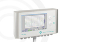



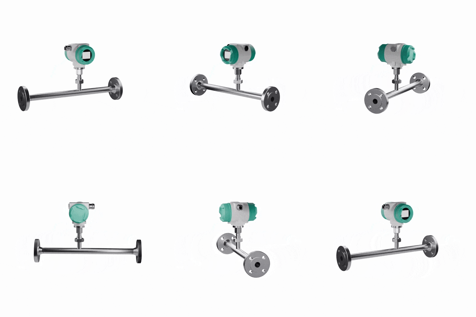
Industrial gas flow meter for critical applications — VA 570
-min.jpg "Промышленный расходомер газов — VA 570")
-min.jpg "Промышленный расходомер газов — VA 570")
-min.jpg "Промышленный расходомер газов — VA 570")
-min.jpg "Промышленный расходомер газов — VA 570")
-min.jpg "Промышленный расходомер газов — VA 570")
-min.jpg "Промышленный расходомер газов — VA 570")
-min.jpg "Промышленный расходомер газов — VA 570")
 Спецификация VA 570
Available on request
Delivery across Russia
Order phone: +7(800)777-18-50
Description
The new VA 570 gas flow meters use the thermal anemometric measurement principle. Thanks to this, no additional temperature and pressure measurements are required.
Due to its reliable design, cast aluminum housing, and durable sensor made of stainless steel 1.4571, the new VA 570 gas flow meter is suitable for critical industrial applications. The ATEX version of the device can be used in explosive environments. For measuring flow, for example, of natural gas, a version of the flow meter with DVGW approvals is available.
Unlike the previously used bridge circuit, the new electronics record data digitally. This has increased measurement accuracy and reduced response time over a wide temperature range up to 180°C. The wide dynamic range of 1…1000 allows measurement at both very low and very high gas flow velocities (up to 224 m/s).
The VA 570 is equipped with a Modbus interface as a standard output signal, allowing transmission of parameters such as Nm³/h, Nm³, Nm/s, Nl/min, Nl/s, kg/h, kg/min, ft/min, °C, etc. All parameters can be configured directly (from the display), as well as using the PI 500 handheld device or Service Software. Additionally, the device has 2 analog output signals 4...20 mA for flow and temperature, as well as a galvanically isolated pulse output for transmitting accumulated gas flow data.
Remote diagnostics of the device can be performed via Modbus, allowing verification and, if necessary, modification of all significant parameters. For example, if operating conditions change, it is possible to adjust gas type values, internal pipeline diameter, scaling, zero point, or disable air leak compensation.
The VA 570 is supplied with an integrated measuring section. Measuring sections are available in flange versions or with R or NPT threads. A feature of the device is the removable measuring part. The measuring module can be extracted for calibration or cleaning without dismantling the entire flow meter. After removing the measuring part, the opening in the section can be closed with a protective cap (accessory). The guiding lug ensures precise installation of the measuring part relative to the flow. This helps prevent loss of accuracy.
- Specifications
- Overall Drawing
- Connection diagram
- Applications
| Characteristic | Value |
| Accuracy | ± 1.5 % of measured value ± 0.3 % FS option: ± 1.0 % of measured value ± 0.3 % FS |
| Reference accuracy conditions | Ambient temperature 22°C ± 2°C, system pressure 6 bar |
| Repeatability | 0.25 % of measured value with correct installation (sensor position, straight pipeline sections) |
| Measurement principle | Thermal mass flow sensor, measurement principle based on cooling of the heated PT45 sensor by passing air. Ambient air temperature is measured by PT100 sensor. Additional temperature and pressure compensation is not required |
| Response time | t90 < 3 s |
| Operating temperature of probe / display | -40...180 °C for probe 0...350 °C for probe (high-temperature version) -40...70°C for display -40...120°C for ATEX version |
| Possible settings via display, PI 500 device or Service Software: | Units of measurement (Nm³/h, Nm³/min, Nl/min, l/s, ft/min, cfm, kg/h, kg/min), gas type, internal diameter, reference conditions (°C/°F, mbar/hPa), zero point correction, disabling leak air accounting, scaling of analog output 4...20 mA, pulse output/alarm, error codes, etc. |
| Output signals | Modbus RTU, 2 x 4...20 mA active/passive for °C and Nm³/h, Modbus TCP, HART Profibus DP, Profi Net, galvanically isolated pulse (pulse value adjustable), relay max. 48 VDC 0.5 A |
| Load | 500 Ohm |
| 3 built-in counters | 1 x totalized flow (non-resettable), 1 x totalized flow (resettable), flow counter for a set time period (resettable, value from 1 minute to 1 day, e.g. flow counter for 1/2 hour, for a day, etc.) |
| Calculation of average values | for all parameters over a time interval from 1 minute to 1 day, e.g. average value for 1/2 hour or for 1 day |
| Protection class | IP 67 |
| Material | Housing: cast aluminum Probe: stainless steel 1.4571, glass |
| Operating pressure | 16 bar Special version: 40 bar |
| Power supply | 12...36 VDC, 5 W |
| Special versions | ATEX II 2G Ex d IIC T4, DVGW |
Industrial gas flow meter version with threaded connection:

| Thread connection | Outer pipe diameter | Inner pipe diameter | L (mm) | L1 (mm) | H (mm) | H1 (mm) | A (mm) |
| 1/2“ | 21.3 | 16.1 | 300 | 210 | 176.4 | 165.7 | 20 |
| 3/4“ | 26.9 | 21.7 | 475 | 275 | 179.2 | 165.7 | 20 |
| 1“ | 33.7 | 27.3 | 475 | 275 | 182.6 | 165.7 | 25 |
| 1 1/4“ | 42.4 | 36 | 475 | 275 | 186.9 | 165.7 | 25 |
| 1 1/2“ | 48.3 | 41.9 | 475** | 275 | 189.9 | 165.7 | 25 |
| 2“ | 60.3 | 53.1 | 475** | 275 | 195.9 | 165.7 | 30 |
| **Shortened measuring section! Maintain the length of straight sections before the device (10 inner diameters) | |||||||
Industrial gas flow meter version with flange connection:

| Measuring section | Outer pipe diameter | Inner pipe diameter |
L (mm) | L1 (mm) | H (mm) | H1 (mm) | Flange DIN EN 1092-1 | ||
| ØD (mm) | ØK (mm) | n x ØL | |||||||
| DN 15 | 21.3 | 16.1 | 300 | 210 | 213.2 | 165.7 | 95 | 65 | 4 x 14 |
| DN 20 | 26.9 | 21.7 | 475 | 275 | 218.2 | 165.7 | 105 | 75 | 4 x 14 |
| DN 25 | 33.7 | 27.3 | 475 | 275 | 223.2 | 165.7 | 115 | 85 | 4 x 14 |
| DN 32 | 42.4 | 36 | 475 | 275 | 235.7 | 165.7 | 140 | 100 | 4 x 18 |
| DN 40 | 48.3 | 41.9 | 475** | 275 | 240.7 | 165.7 | 150 | 110 | 4 x 18 |
| DN 50 | 60.3 | 53.1 | 475** | 275 | 248.2 | 165.7 | 165 | 125 | 4 x 18 |
| **Shortened measuring section! Maintain the length of straight sections before the device (10 inner diameters) | |||||||||

| Terminal | Contact number | Purpose |
| X1 Power supply |
1 | VB - (GND) |
| 2 | VB+ (12V – 36 Vdc) | |
| X2 Modbus |
1 | Modbus (B) |
| 2 | Modbus shielding | |
| 3 | Modbus (A) | |
| X3 Analog output |
1 | Pulse / alarm signal* |
| 2 | Pulse / alarm signal* | |
| 3 | Direction input | |
| 4 | GND | |
| X4 Current output 1 |
1 | I- Active* |
| 2 | I+ Active* | |
| X5 Current output 2 |
1 | I- Active* |
| 2 | I+ Active* |
*All analog outputs are galvanically isolated
**Passive analog outputs are also optionally available.
You may find useful
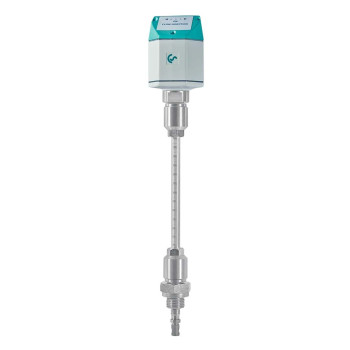
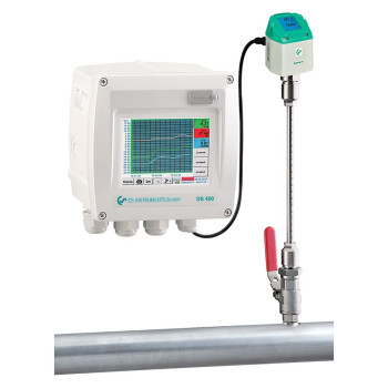
-min.jpg "Multichannel Digital Data Recorder — DS 500 buy at a low price in St. Petersburg")
-min.jpg "Multichannel Digital Data Recorder — DS 500 Mobile buy at a low price in St. Petersburg")
-min.jpg "New dew point sensors with digital and analog outputs — FA 510 / FA 515 competitive prices in Saint Petersburg")