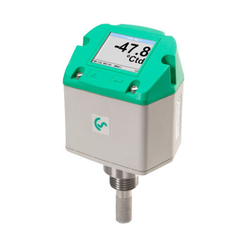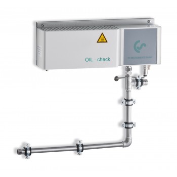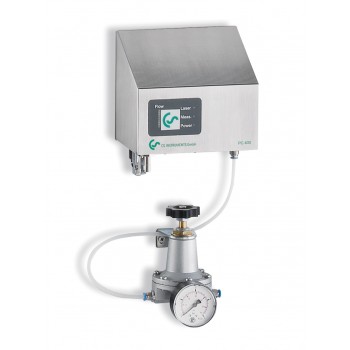
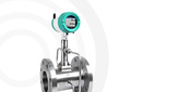



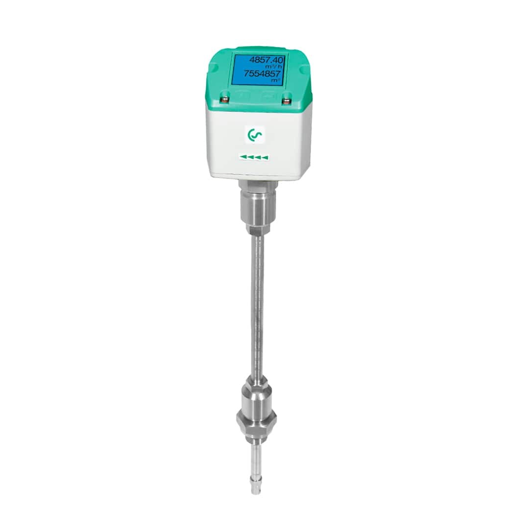
Convenient and accurate air and gas flow meter with digital interface — VA 500
-min.jpg "Удобный и точный расходомер воздуха и газов с цифровым интерфейсом — VA 500")
-min.jpg "Удобный и точный расходомер воздуха и газов с цифровым интерфейсом — VA 500")
-min.jpg "Удобный и точный расходомер воздуха и газов с цифровым интерфейсом — VA 500")
-min.jpg "Удобный и точный расходомер воздуха и газов с цифровым интерфейсом — VA 500")
-min.jpg "Удобный и точный расходомер воздуха и газов с цифровым интерфейсом — VA 500")
-min.jpg "Удобный и точный расходомер воздуха и газов с цифровым интерфейсом — VA 500")
-min.jpg "Удобный и точный расходомер воздуха и газов с цифровым интерфейсом — VA 500")
-min.jpg "Удобный и точный расходомер воздуха и газов с цифровым интерфейсом — VA 500")
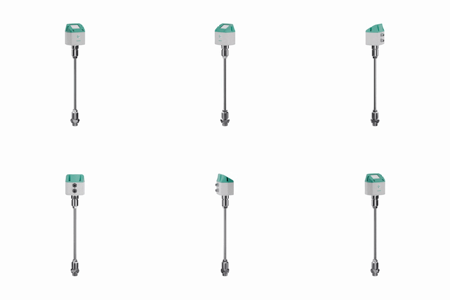
 Спецификация VA 500
Available on request
Delivery across Russia
Order phone: +7(800)777-18-50
Description
Thanks to its ease of installation, the flow meter is an ideal tool for conducting pneumatic audits – it is absolutely effortless to move one flow meter between different sections without shutting down the system. The flow meter is installed using a standard 1/2' ball valve even in a pressurized system. During installation and removal, the protective ring prevents the probe from being ejected from the pipe due to pressure. For installation on pipelines of various diameters, there are VA 400 versions with probe lengths from 120 to 700 mm. The flow meter can be installed on pipes with an internal diameter of 1/2' and above. The scale engraved on the probe facilitates precise alignment of the sensitive element at the center of the pipeline. The maximum immersion length corresponds to the probe length. Thus, for the VA 400 with a probe length of 220 mm, the maximum immersion length is also 220 mm.
Thanks to the wide measurement range, the device can be used even for applications involving extremely high flow rates (large gas volumes with a small diameter). The measurement range depends on the internal diameter of the pipe (see the table in the specification).
The flow meter has a robust housing. Available in versions with and without a display. The display can show the current flow in m3/h and the accumulated flow in m3.
By changing the device settings using software, one device can be used to measure the flow of various gases. The sensor can measure the flow of air, nitrogen, natural gas, argon, CO2, oxygen, and other gases.
Advantages
- RS 485 interface, Modbus-RTU by default;
- Built-in display for m³/h and m³ • Can be used on pipelines from 1/2“ to 12“;
- Simple installation under pressure • Analog output 4...20 mA for m³/h and m³/min;
- Pulse output for m³;
- Internal diameter value is set from the display;
- Resettable accumulated flow counter;
- From the display, the following can be configured: gas type, reference conditions, °C and mbar, 4...20 mA scaling, pulse value.
- Specifications
- Overall Drawing
- Connection diagram
- Applications
| Characteristic | Value |
| Measurable parameters | m³/h, l/min (1000 mbar, 20°C) for compressed air. Nm³/h, Nl/min (1013 mbar, 0°C) for gases |
| Set from display | m³/h, m³/min, l/min, l/s, ft/min, cfm, m/s, kg/h, kg/min |
| Set using buttons | Diameter for flow calculation, counter can be reset |
| Measurement principle | Calorimetric |
| Sensor | Thermal mass sensor |
| Measured medium | Air, gases |
| Gases settable with DS400, DS500, PI500 | Air, nitrogen, argon, nitric oxide, CO2, oxygen |
| Measurement range | See table in specification |
| Accuracy | ± 1.5 % of measured value ± 0.3 % FS Optional: ± 1.0 % of measured value ± 0.3 % FS |
| Operating temperature | -30...110 °C for probe -30...80 °C for housing |
| Operating pressure | up to 50 bar |
|
Digital output |
RS 485 interface, Modbus RTU |
| Analog output | 4...20 mA for m³/h or l/min; on request: scaling for cfm, m³/min, l/min, l/s, ft/min, m/s |
| Pulse output | 1 pulse per m³ or per liter, galvanically isolated |
| Power supply | 24 VDC |
| Load | < 500 Ohm |
| Housing material | Polycarbonate |
| Probe | Material – stainless steel, 1.4301 installation length 220 mm, Ø 10 mm |
| Connection thread | G 1/2“ |

| Connector A | Connector B |
 |
 |
| Pin Number | Pin Color | Function (Connector A) |
Function (Connector B) |
| Pin 1 | brown | +VB | NC |
| Pin 2 | white | RS 485 (A) | GND |
| Pin 3 | blue | -VB | DIR |
| Pin 4 | black | RS 485 (B) | Pulse (galvanically isolated) |
| Pin 5 | gray | I+ 4..20 mA |
Pulse (galvanically isolated) |
| Designation | Comment |
| -VB | Power supply negative 0 V |
| +VB | Power supply positive 12...30 VDC |
| I + | Current signal 4..20 mA – selected measurement |
| RS 485 (A) | Modbus RTU A |
| Pulse | Pulse output for accumulated flow |
| NC | Do not connect to voltage and/or ground. Cut and insulate the contacts |
| RS 485 (B) | Modbus RTU B |
You may find useful
-min.jpg "Multichannel Digital Data Recorder — DS 500 buy at a low price in St. Petersburg")
-min.jpg "Multichannel Digital Data Recorder — DS 500 Mobile buy at a low price in St. Petersburg")
-min.jpg "New dew point sensors with digital and analog outputs — FA 510 / FA 515 competitive prices in Saint Petersburg")