







The cost of energy increases every year. The higher the energy costs of an enterprise, the greater the overall expenses. There are many ways to increase energy efficiency. One of them is voluntary certification according to GOST ISO 50001-2012. The purpose of certification is to enable the development of systems and processes necessary to improve energy performance, including energy efficiency and energy consumption.
In this article, we will present specific examples of energy management schemes based on the PDCA system (Plan, Do, Check, Act) for compressed air systems from CS Instruments.
Step 1: Operational control of costs related to energy and compressed air.
 The first step is to install accurate compressed air flow meters at all main points of the system to ensure reliable measurement data. The devices are installed directly in the main pipeline of the compressor unit (in the compressor room). At the first step, compressed air consumption in the supply line is best recorded using a data logger. Pneumatic lines leading to individual end users of compressed air are only accounted for in the second step.
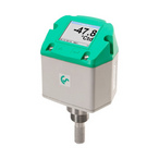
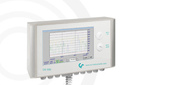
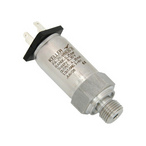
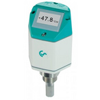
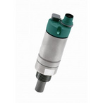
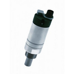
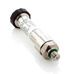
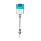
As shown in the example, the DS 500 data logger, installed in the compressor room during compressed air production, directly determines and records data from the following devices: flow sensor VA 500 – compressed air consumption; dew point sensor FA 510 – dew point or pressure dew point; power meters PM 210 / PM 710 – current consumption of current and voltage; and additionally, pressure – pressure sensor.
In practice, such compressed air measurements should be performed for at least one week. Ideally, "from Friday to Friday" to obtain consumption data for the compressor unit over a full production period. Compressed air leaks are detected very quickly, especially on weekends. During production shutdown, compressed air consumption should be practically "zero m³/h," which is actually impossible. The compressor load behavior on weekends is such that compressors operate only to maintain "leak pressure," and a peak in compressed air consumption can be observed at the beginning of the week.
Step 2: Localization of leaks and losses of compressed air.
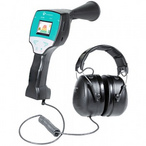
 In the second step, leaks and losses of compressed air are localized. For this purpose, pneumatic lines of the most important consumers are included in the compressed air analysis cycle. First, the largest consumers of compressed air must be identified. They should be highlighted as separate consumers, such as workshops, floors, production lines, or even individual machines. After determining compressed air consumption for each consumer, it quickly becomes clear where and what costs are associated with compressed air production. Using modern ultrasonic devices, such as the ultrasonic leak detector LD 400 from CS Instruments, even very small leaks or losses of compressed air can be quickly and easily detected, including during ongoing production.
Use this opportunity to reduce your leaks, and consequently your compressed air consumption, and thus your current expenses – through targeted compressed air analysis. Installing data loggers such as the DS 500 in the most important pneumatic lines helps facilitate tracking of compressed air consumption (and related costs) as well as leaks. Additionally, measurement data can be reliably stored on the company server for many years. Threshold exceedance alarms operate online, providing immediate recognition of sudden peaks in compressed air consumption caused by line defects or damage to pneumatic hoses. The responsible employee is notified directly via SMS or email. Pneumatic valves can be closed using signal relays.
Leaks of compressed air can be partially eliminated quite easily, namely by replacing non-tight pneumatic connections or built-in connectors, or by tightening screw connections, such as compressed air flanges. This is much more problematic in the case of pneumatic systems with long lines, as well as with too small internal diameters of compressed air pipelines, bends and system line upgrades, pressure losses in filters and dryers. Too small internal diameters of compressed air pipes lead to high flow velocity, which is unprofitable in terms of cost-effectiveness, and consequently to pressure losses.
On the other hand, reducing the line pressure by 1 bar can save approx. 8% energy. Contaminated filters cause undesirable pressure drops and pressure loss in the pipeline. To reduce these inefficient energy costs and keep them under control in the long term, not only compressed air flow meters should be used, but also pressure drops in the most important filters should be monitored using pressure sensors and data loggers. In addition, thanks to the use of a logger, filter replacement intervals can be optimally determined. To ensure uninterrupted production, compressed air dryers are necessary. Failures of compressed air dryers (refrigeration, membrane, or adsorption dryers) lead to condensation, corrosion, and production downtime. With the data logger DS 500, CS Instruments offers customer-oriented solutions for evaluating and recording all necessary parameters of the compressor unit.
Step 3: Adaptation of solutions
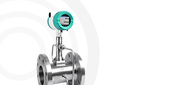
 If you have identified and analyzed the energy-saving potential of the main pneumatic line of the compressor unit, you can transfer the results of the compressed air analysis to the entire pipeline system. This experience should help save energy when planning and expanding the pneumatic system. Therefore, it is necessary to carefully forecast how economically beneficial it can be to replace a pneumatic line with too small a diameter with a new pipeline system with a larger internal diameter. Outdated measurement technology (e.g., flow measurements using differential pressure, vortex flow meters, etc.), which results in limiting the internal diameter of the compressed air pipeline, should be replaced with technology using modern flow meters without reducing pipe diameter.
Incorrectly closing ball valves should be replaced. Non-closing couplings should also be replaced with new ones, but these are just some examples of possible optimization. Use steps 1-3 for continuous and thorough development of further solutions within your entire pneumatic system. An optimized pneumatic system saves money, which is an important point with the constant increase in energy costs.
Step 4: Monitoring optimization
 The pneumatic system requires continuous monitoring. After completing steps 1-3 (recording compressed air consumption and energy costs, locating leaks and compressed air losses, transferring solutions to the entire pneumatic system), compressed air analysis, as a continuously performed process, should be continued as the most important step 4. For this purpose, an employee responsible for energy savings in pneumatic lines should be appointed in each department.
Contact the specialists of Izmerkon to select the optimal set of equipment for energy management according to ISO 50001, taking into account all the features of your production.
_80x0_e6f.jpg "Pressure Transmitter Series 23SX-H2")
1)_80x0_e6f.jpg "Happy Defender of the Fatherland Day!")
_80x0_c25.jpeg "Radar Level Meter IZMERKON RL 37")


-min_146x146_c23.jpg "Стрелка")