


Since 1904, Des Moines and Mississippi Levee No. 1 have provided flood control and irrigation regulation along the Mississippi River near Alexandria, Missouri, through a series of designed levees, ditches, and pumps. They are governed by a Board of Directors consisting of 5 representatives, and design services are provided by Klingner & Associates Engineers (Quincy, Illinois).
Since 2012, Navionics Research has proudly served this District as its Control Systems Subcontractor. The local monitoring and controllable equipment includes level measuring instruments, two 400 HP pumps with interacting variable frequency drives, power meters, voltmeters, and a precipitation analyzer. Through the system's user interface, District staff can monitor status and operational data; they also receive text messages on cell phones and email alerts about key events such as pump start/stop, high water level registration, or power outages.
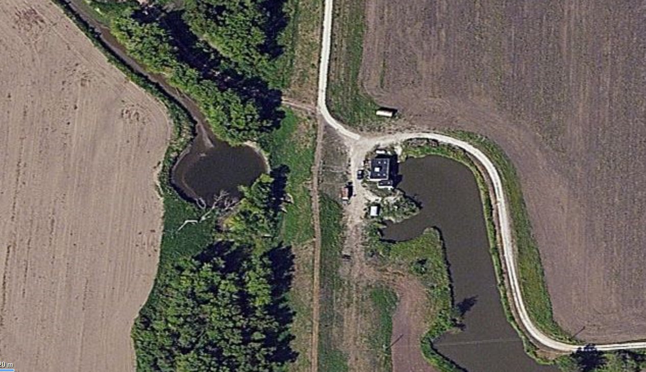
Pumping station. Levee (center), ditch (right), channel to river (left).
The key to the system’s effective operation is accurate and reliable water level measurement both in the ditch and in the river. The water level in the ditch is important because pumps turn on when the ditch reaches the high-level threshold and turn off when the ditch reaches the low-level threshold. The water level in the river is also important because some pumps are limited to a narrow pressure head range. Both levels, combined with pump speed, pump characteristic curves, and "flow-head" data, can be used to calculate flow power and summarize results. However, this topic deserves a separate article and will not be covered here. There are various control and measuring instruments that allow water level monitoring. Nevertheless, this article will focus primarily on the Pneumatic Bubbler Transducer. Our system involves a pneumatic pump, air measurement lines, sensors, valve components, and control systems.
The submerged sensor method, which was originally installed on the Levee but recently replaced during modernization, has several drawbacks. First, submerged sensors are usually located at significant distances from the Control Point, making them more vulnerable to lightning damage and grounding grids. Moreover, any electronic device submerged in water can eventually fail due to water ingress, even if the device is rated IP68 and intended for this purpose. Additionally, using a submerged sensor requires a qualified installation organization that understands potential hazards and how to avoid them.
The Pneumatic Bubbler Transducer method does not require an IP68-rated pressure sensor since the sensor is installed in the dry environment of the Control Point. Furthermore, pressure sensors are installed in one housing (or nearby) with the main control post, reducing the risk of lightning damage and grounding grid issues. The diagram below illustrates the operation of the Pneumatic Bubbler Transducer level measurement system:
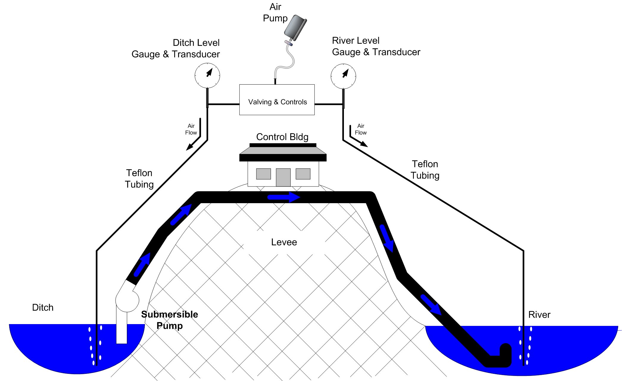
Level determination – based on polyethylene tubes conditioned by the Bubbler System
The following photos show the Pneumatic Device installed in a special housing and connected to the main control panel:
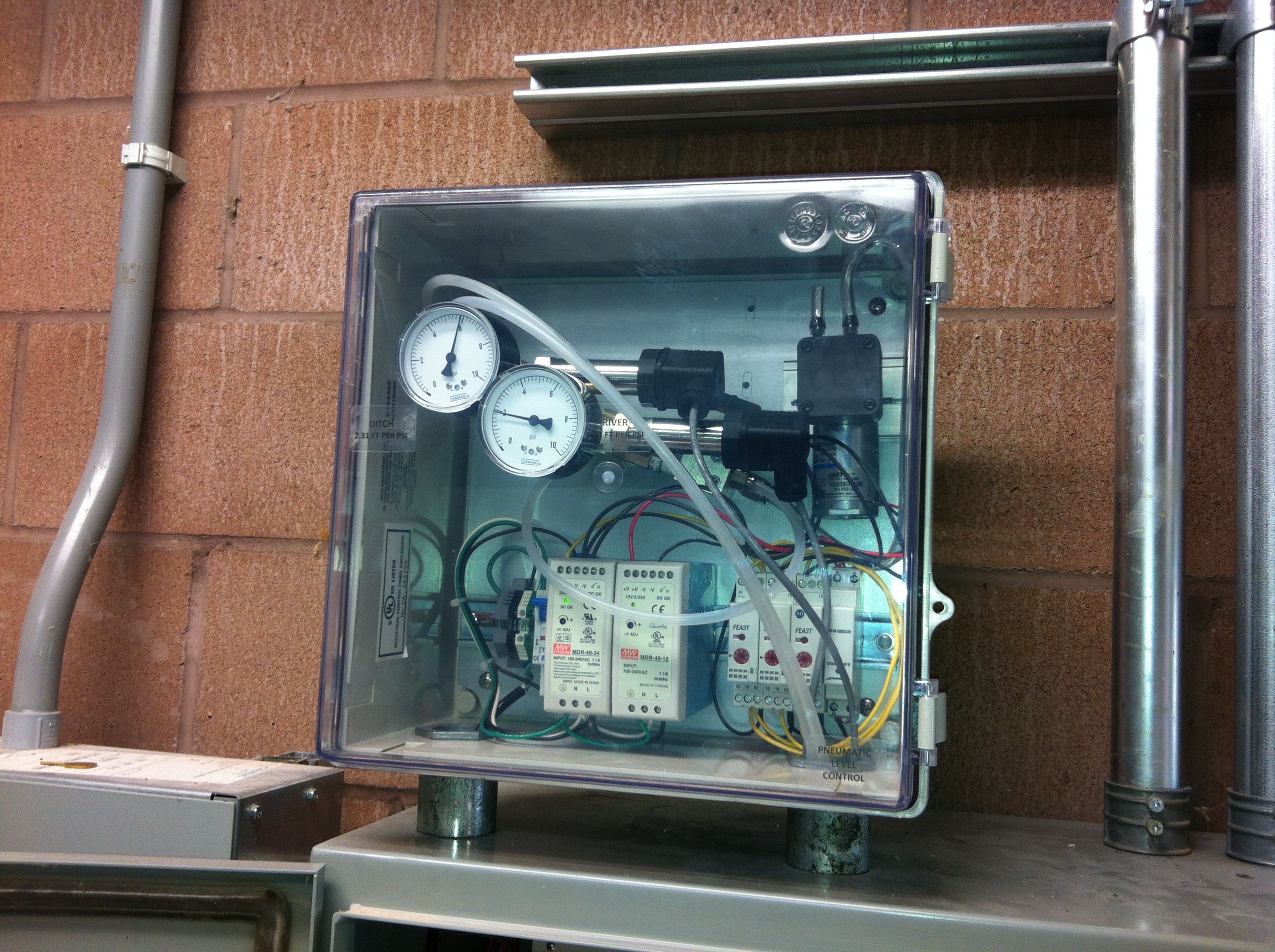
Pneumatic pump, sensors, valves, and control system.
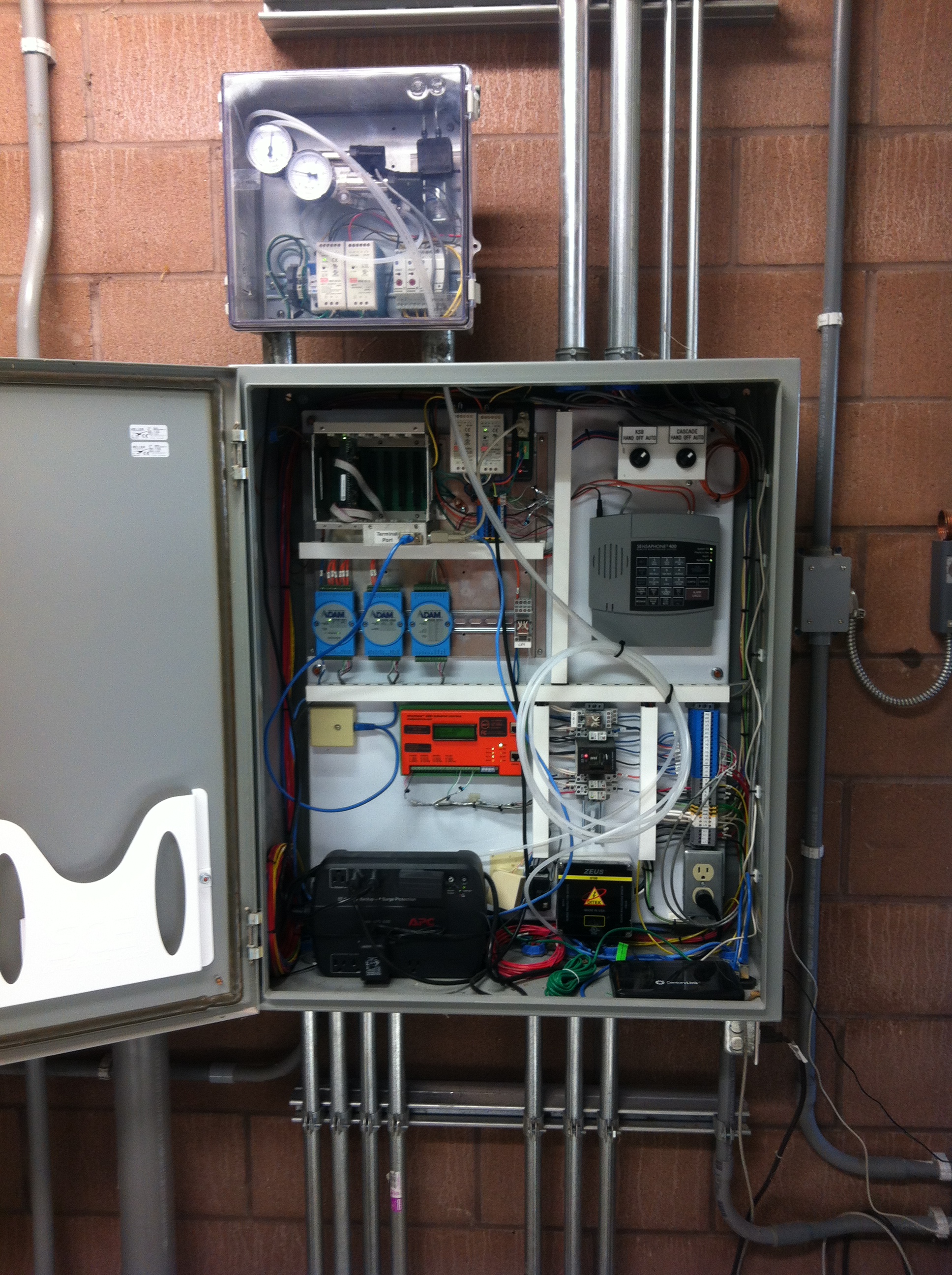
Control and telemetry unit. Note the relative simplicity of connection thanks to the high degree of networked, distributed measuring equipment.
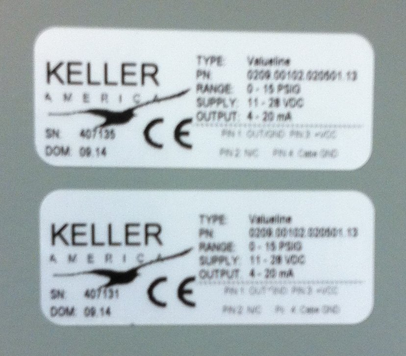
Pressure sensors: Keller ValueLine, 0...15 ft/sq. inch. Output signal: 4...20 mA
Installation photos...
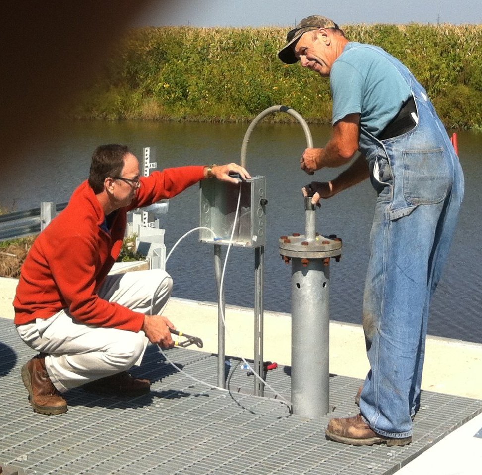
Installation of polyethylene tubes into the protective tube on the ditch side. Jim Mimlitz, Navionics Research (left), Hank Borrenpol, Okawville Electric (right).
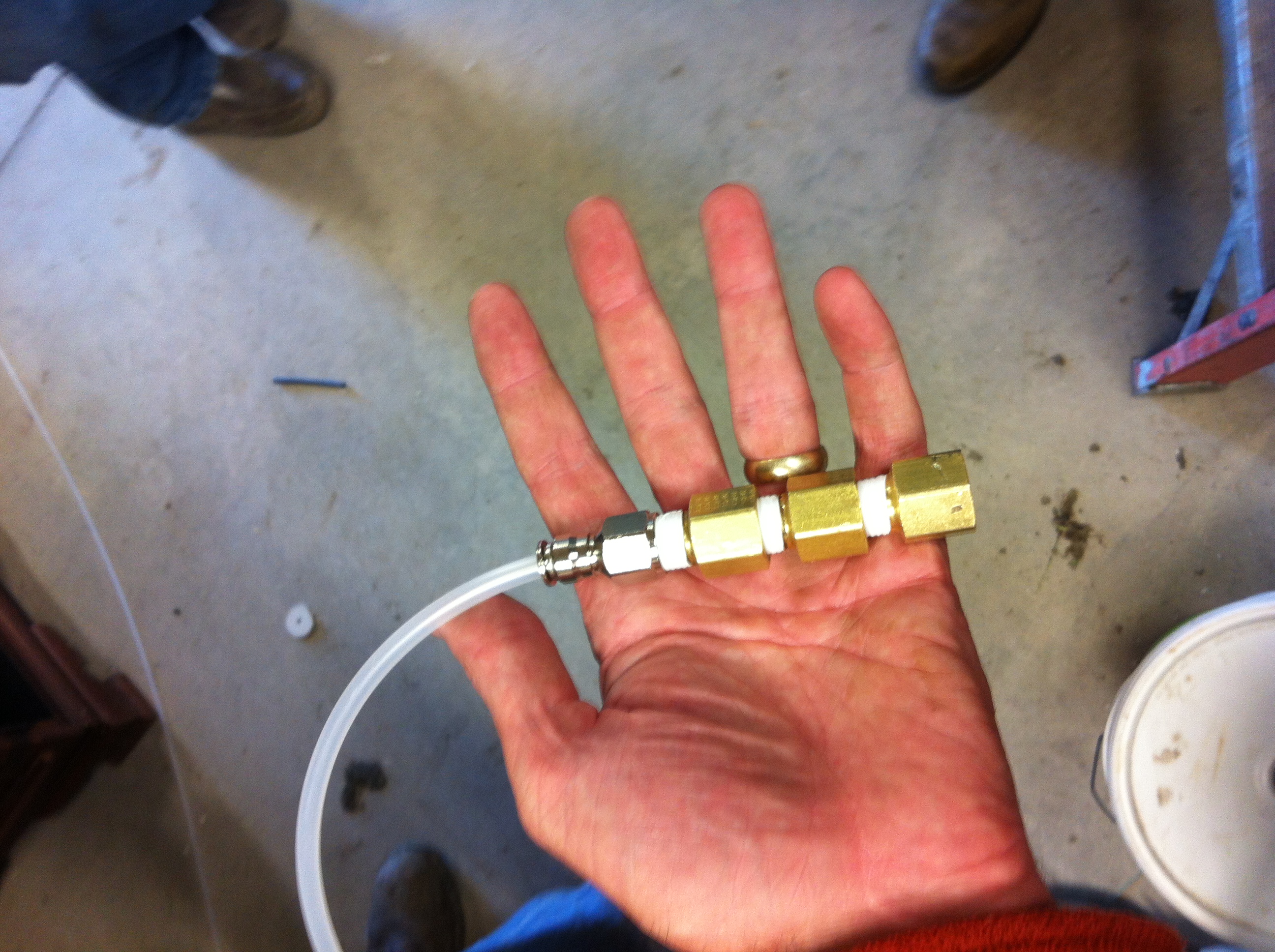
The end of the polyethylene tube is weighted so that it does not rise to the surface when filled with air.
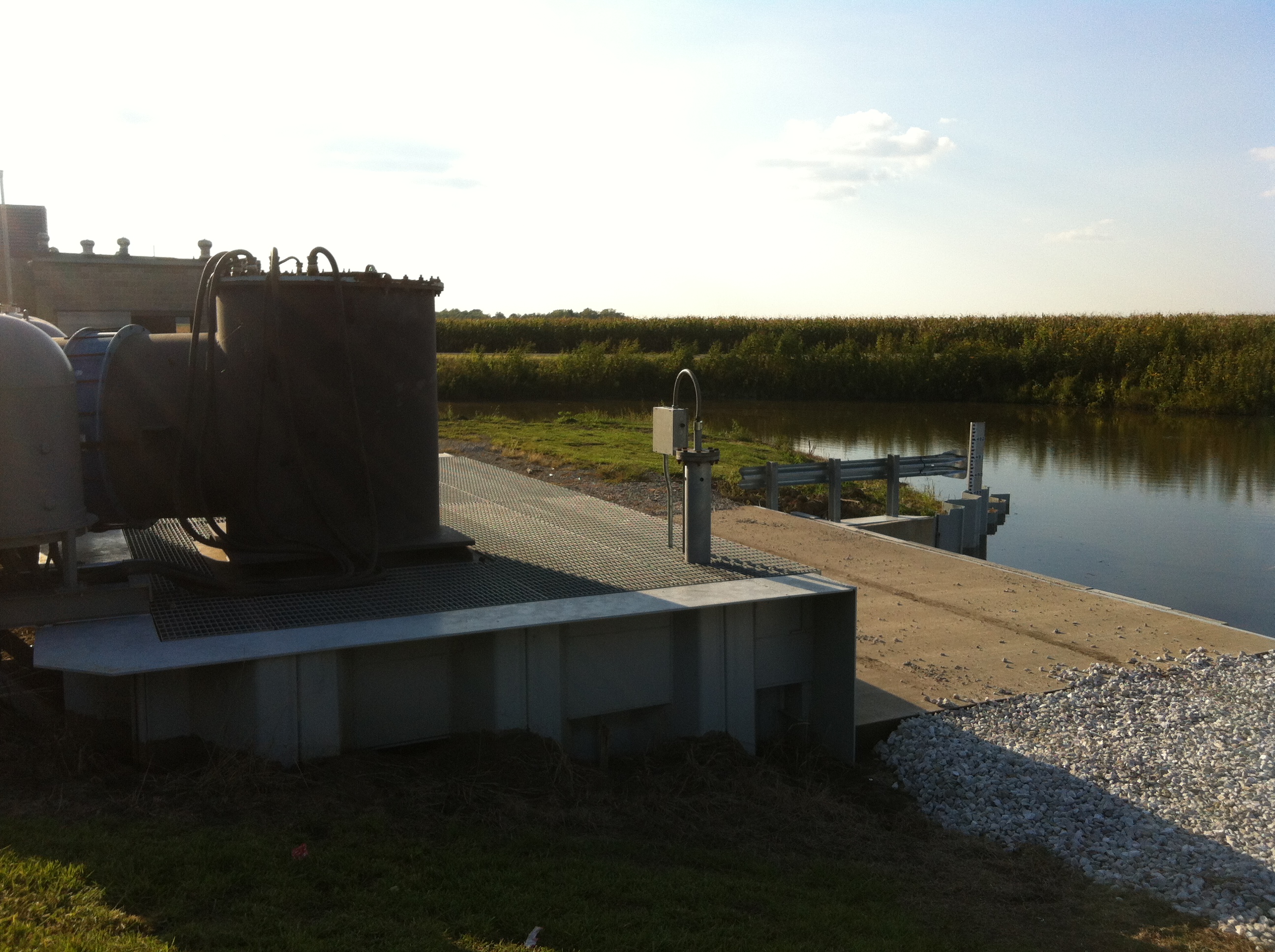
Protective tube on the ditch side after tube installation.
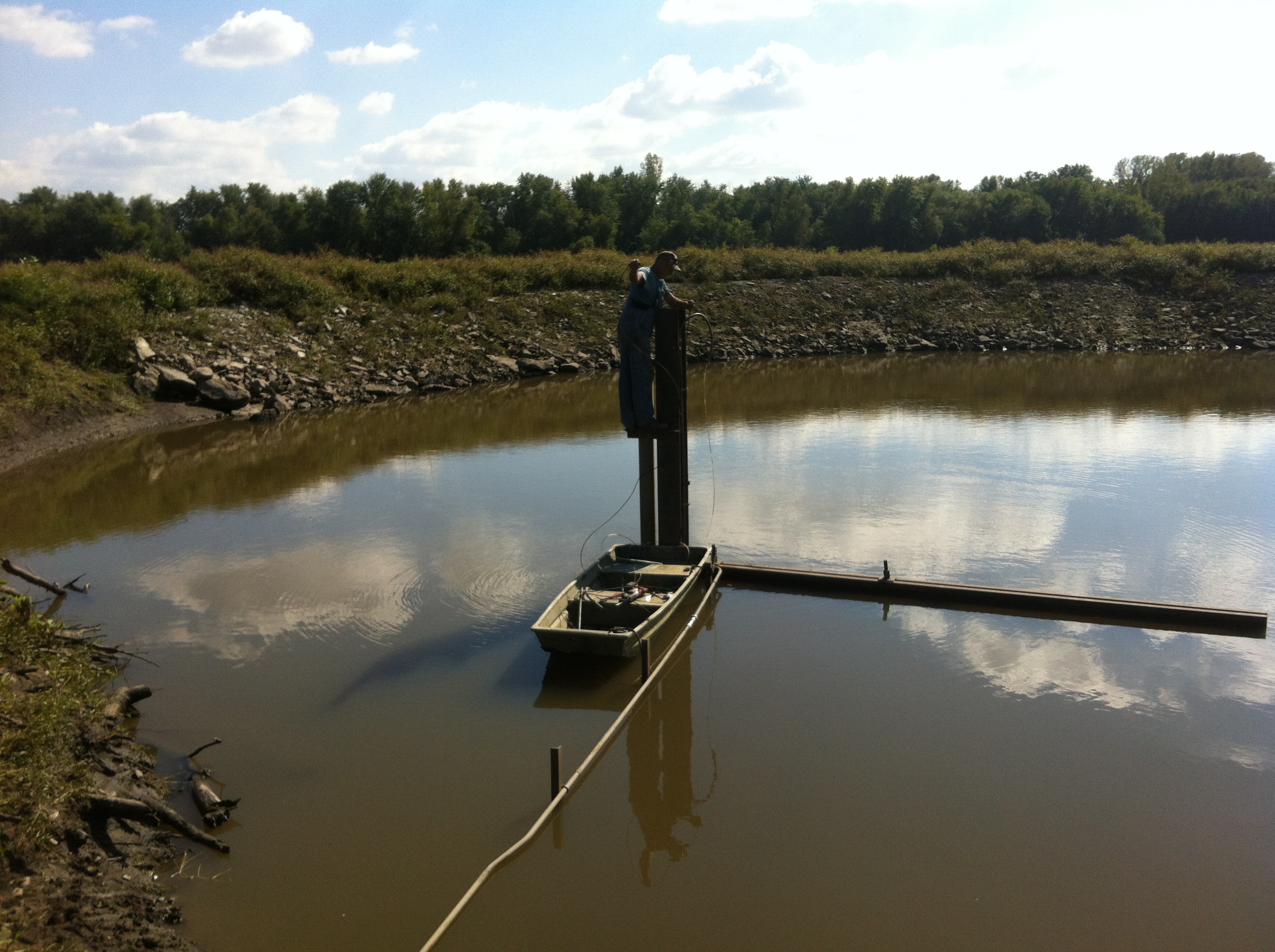
Installation of the tube from the river side. Hank Borrenpol, Okawville Electric.
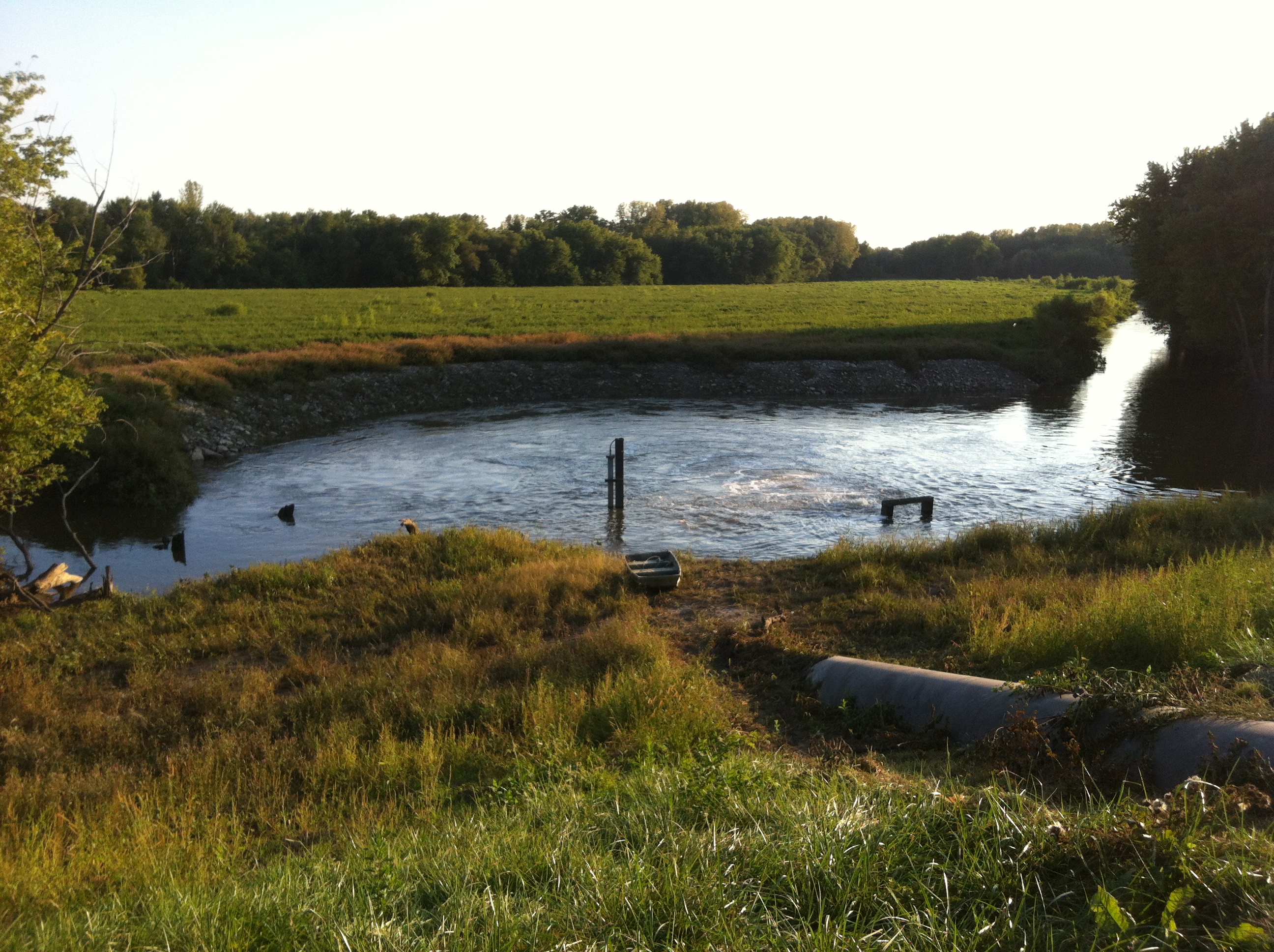
Measuring tube from the river side, after installation. Note the visible flow from the pump tube.
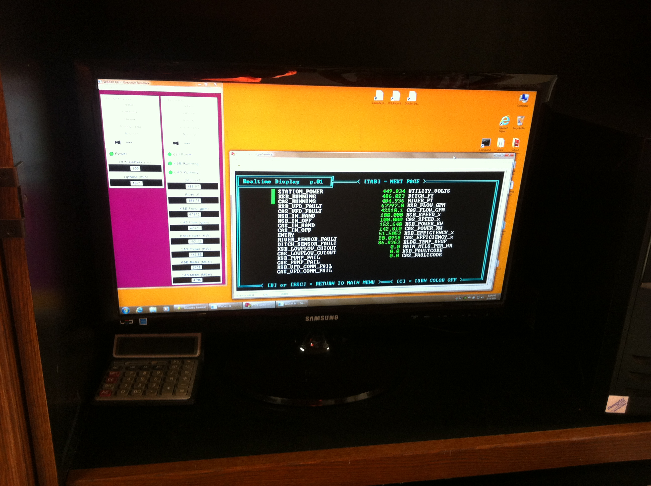
The telemetry system indicator shows real-time measurement data.
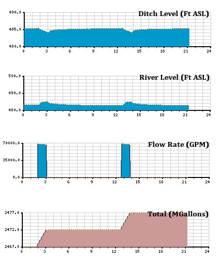
Telemetry result charts. Results shown several days after installation of Pneumatic Bubbler Level Sensing.
It is important to note that this measurement method can be applied not only for dam monitoring but also for drinking water. For example, water treatment plants using surface water bodies can use this system to monitor lake or river levels during raw water intake. Comprehensive water treatment plants can use this system to monitor groundwater levels in wells. In any case, if the measured level is too low, the control system is programmed to automatically shut off the pump(s) to prevent pump cavitation. Another potential application of this system could be liquid level monitoring in chemical tanks at filtration/cleaning facilities.
Notable improvements made after the initial installation:
- Added an adjustable pressure regulator to limit the pressure coming from the compressor pump.
- Added pressure dampers for each sensor and measuring device - thereby stabilizing readings during compressor pumping.
- Used more durable compression fittings instead of quick-disconnect couplings for submerged copper fasteners (weights) at the ends of polyethylene tubes.
- Added an incoming air filter for the compressor pump.
_80x0_e6f.jpg "Pressure Transmitter Series 23SX-H2")
1)_80x0_e6f.jpg "Happy Defender of the Fatherland Day!")
_80x0_c25.jpeg "Radar Level Meter IZMERKON RL 37")


