


Vortex Flowmeter
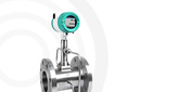
The operation of the vortex flowmeter is based on measuring the frequency of oscillations that occur in the flow during vortex formation. A bluff body, most often trapezoidal in shape, is installed in the path of the air flowing through the pipeline. This obstacle creates a chain of vortices in the flow, called a Karman vortex street. The distance between vortices is constant and depends on the size of the obstacle, while the vortex frequency is proportional to the flow velocity. Below the bluff body, an element is installed that indicates the passing vortices. Usually, this role is performed by a piezoelectric transducer that detects the frequency of pressure oscillations created by the passing vortices. Detection can also be carried out using a thermal anemometer, ultrasonic, or optoelectronic transducer. The frequency of pressure changes allows calculating the flow velocity and, consequently, the flow rate.
The advantage of this type of flowmeter is the absence of moving parts and resistance to contamination. Nevertheless, this flowmeter is not suitable for measuring low velocities, has relatively high pressure loss, and requires temperature and pressure compensation.
Coriolis Flowmeter
Coriolis flowmeters are equipped with one or two U-shaped tubes that oscillate due to external vibrational excitation generated by a special actuator. In the absence of flow, the tube oscillations occur uniformly and synchronously. However, when gas flows through the tube, the Coriolis force causes a phase shift in the oscillations: different parts of the tube begin to deflect in different directions. The degree of deflection is proportional to the gas flow velocity. Sensors located at the inlet and outlet of the flowmeter register the nature of these oscillations, and then these values are converted into flow velocity and flow rate.
The advantages of this type of device include high accuracy, operation under any flow condition in both directions, and no moving parts. Disadvantages include significant pressure losses, high cost, large weight, and size.

Thermal Flowmeters
The measurement principle is based on the dependence of heat dissipation from a heated element placed in the flow on the flow velocity. Depending on how the measurement is performed, thermal flowmeters are divided into thermal anemometric and calorimetric types.
Thermal anemometric flowmeters
Thermal anemometric flowmeters are based on the principle of measuring heat loss by a body due to the flow passing around it. In this design, the sensitive element consists of two resistive elements. The first measures the temperature of the medium. The second is constantly maintained at a temperature a certain amount above the medium temperature. The gas flow passing by the second sensitive element cools it, so more energy is required to maintain its temperature. The higher the flow velocity, the stronger the cooling of the sensitive element and the more power is needed for heating. Thus, by considering the electrical power consumed for heating, the sensor determines the flow velocity proportional to it, which is then converted into flow rate.
In some designs, the current supplied to heat the sensitive element is constant. In this case, the resistance of the sensitive element, which changes depending on the flow velocity, is recorded. The flow temperature is measured by a second sensor located downstream in the flow.
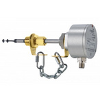
Examples of thermal anemometric flowmeters include models such as VA 400, SS 20.500, or SS 20.600.
Calorimetric flowmeters
In this case, the design includes a heating element and two temperature sensors located downstream and upstream relative to the heater. The air passing near the heating element becomes warmer, and this temperature change is detected by the sensor located downstream. By comparing its readings with those of the thermometer located upstream in the flow, the device calculates the gas velocity. Since the temperature sensors are located on both sides of the heating element, this flowmeter design also allows determining the direction of gas flow.
An example of calorimetric flowmeters includes devices such as SS 20.400
and SS 20.415.Thermal flow meters have many advantages. They provide direct measurement of flow normalized to standard conditions and do not require temperature and pressure compensation. The measurement range of these devices is extremely wide, and they can be used even at very low flow velocities. These sensors do not create pressure drops. In addition, they can be not only insertion type but also immersion type, which significantly simplifies installation (which can be done even in an operating system) and makes them applicable in pipelines of very large diameters. Thermal flow meters are also quite reliable as they have no moving parts. Finally, these devices are relatively inexpensive compared to most other flow meters.
Features include the requirement for installation on relatively long straight sections of pipeline (at least 10 pipe diameters), as well as deviations in measurement results in case of condensation.
Previous parts:
Gas flow meter classification – part 1
Gas flow meter classification – part 2
You can select a gas flow meter suitable for solving your task in the product catalog or by contacting our technical specialists.
_80x0_e6f.jpg "Pressure Transmitter Series 23SX-H2")
1)_80x0_e6f.jpg "Happy Defender of the Fatherland Day!")
_80x0_c25.jpeg "Radar Level Meter IZMERKON RL 37")


_146x146_c23.jpg "Стрелка")
_146x146_c23.jpg "Стрелка")


