



Compressed air is used in almost every production, but few people know that it is one of the most costly types of energy. Rational use of compressed air has great potential for cost savings. Often, efforts to save are concentrated only on the production of compressed air, that is, on compressors and heat recovery.
Examples of compressed air applications:
• Process air
• Pneumatic start-up
• PET container production
• Pneumatic weaving looms
• Paint and varnish production, etc.
Compressed air is produced by compressing air from the surrounding environment with a compressor. When contaminants from compressed air enter the final product, there is a risk of increased defect rates. Thus, what seems like a cheap solution at first glance leads to significant expenses.
Therefore, it is necessary to treat compressed air after its production, as it may contain moisture, oil, dust particles, and other impurities. The presence of such substances in compressed air, depending on the required purity class, can cause production interruptions and increase operating costs.
In addition to the compressor, tank, and piping system, special equipment is installed for compressed air treatment.
With the help of a dryer, a certain amount of moisture remains in the air, and the dew point temperature value required according to the specifics of use is formed.
Filters provide cleaning of compressed air from oil and other particles. An example of a simple type compressed air system design is shown in Fig. 1.

Fig. 1 Compressed air system components
Compressed air purity classes are defined in the ISO 8573-1 standard. Compliance with quality standards reduces the risk of equipment damage, lowers maintenance costs, and increases the service life of compressed air system equipment. Compressed air purity classes are shown in Fig. 3.
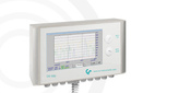
CS Instruments supplies stationary and mobile devices for measuring compressed air quality parameters according to ISO 8573-1:
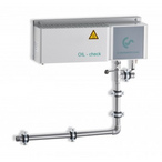
• Measurement of residual oil content using the Oil Check 400 sensor
• Measurement of particle count using the PC 400 counter
• Measurement of dew point temperature using the FA 510 sensor in combination with mobile or stationary data loggers DS 500.

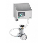
Fig. 2: DS 500 data logger with PC 400, Oil Check 400, FA 510 dew point sensor

Fig. 3: Compressed air purity classes
Leaks of compressed purified air cause excessive costs because additional air must be produced.
 Figure 4 shows the distribution of costs for operating a compressed air system.
Energy costs correspond to the highest share - 73% of all costs.
Therefore, the compressed air system must be designed so that the quantity and quality of produced compressed air meet the standard requirements with the maximum allowable system efficiency.
Figure 5 lists various cost-saving methods offered by the Fraunhofer Society Institute for productions using compressed air. The greatest potential savings are achieved by reducing leak consumption.
Leak detection and elimination account for 42% of total savings in compressed air system operation.

Fig. 5: Cost-saving methods in compressed air system operation
According to research by the NRW Energy Agency, leak consumption of 30% is not uncommon and leads to pressure losses of up to 2 bar, as well as an increase of up to 50% in unused energy.
According to the results of studies conducted by the Fraunhofer Society Institute on behalf of Energie-Schweiz, the degree of leaks at manufacturing enterprises ranges from 15% to 70%.
Water leakage from pipelines, unlike air leakage, is visually noticeable. In addition, the typical whistling sound becomes audible only with significant compressed air leaks in a quiet environment.
In noisy production facilities, such a sound can easily go unnoticed, and the air leak remains undetected. Often, the amount of costs caused by compressed air leaks also remains unknown. Therefore, it is recommended to regularly check for leaks to eliminate them in a timely manner.
The ISO 50001 energy management standard characterizes the PDCA cycle, which can reduce energy costs in production. This cycle can also be applied to compressed air systems.
The PDCA cycle promotes continuous improvement of enterprise operations. The cycle begins with analyzing the initial situation and planning actions followed by their implementation. Verification is carried out by assessing the degree of achievement of set goals and monitoring the obtained indicators. In addition, individual measures taken are evaluated.
The results are then used to determine new optimization actions (Act) if the final goal has not been achieved. Leak detection serves as a means of intermediate verification of the compressed air system's effectiveness. When leaks are detected, measures are taken to eliminate them (Phase Act).

Fig. 6: Energy saving cycle according to ISO 50001
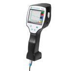
To determine the exact total volume of leaks at the initial situation analysis stage (P), for example, a portable data logger PI 500 with a flow meter VA 500 can be used.
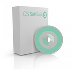
During production downtime, the volume of compressed air leaks is measured and recorded. The obtained data can be processed using the CS Basic software.

Fig. 7: Portable data logger PI 500 with flow meter VA 500
Another measurement option is determining pressure drops during production downtime over a certain period. However, in this case, significant effort is required to determine the volume of compressed air in the entire system, which considerably complicates the use of this method.
This type of measurement is outdated and characterized by large errors because pressure fluctuations and temperature must be measured with exceptional accuracy.
Pressure drop always leads to a temperature decrease. To be able to calculate the volumetric flow rate normalized to standard conditions, extremely precise measurement of absolute pressure and temperature by a pressure sensor is necessary.
The total leak flow value, if present, can be used to calculate the potential annual energy cost savings. For this, information about the cost of compressed air and compressor operating time is also required.
Annual fixed costs for the compressed air system:
• Bank and other financial obligations
• Facility operating costs
Variable costs for the compressed air system:
• Energy costs at full load and during production downtime
• Additional expenses for oil, coolant, etc.
• Maintenance and repair costs of compressors

Fig. 8: Variable costs for the compressed air system
If the annual compressor system output [m³] is divided by the total costs [rub.], the cost of one cubic meter of produced air can be obtained.
The production cost of one standard cubic meter of compressed air ranges approximately from 1.35 rub./n.m3 to 2.42 rub./n.m3, depending on the system type.
Potential energy cost savings [rub./year] = Total leak flow [n.m³/h] * compressed air cost [rub./1 n.m³] * operating hours [h/year]
Since compressed air leaks cannot be detected visually, locating leaks in an enterprise without special equipment is quite problematic.
One of the solutions to this problem is the use of ultrasound, as the leakage of compressed air or gas is accompanied by sound in the corresponding range. Therefore, ultrasonic transducers can be used to detect leaks.
Ultrasound must be converted into an acoustic signal of such a frequency that it can be perceived by the human ear.
For this purpose, a frequency converter is used, which shifts frequencies to a range distinguishable by the human ear.
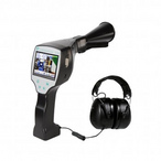
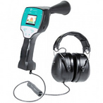
The leak detector LD 500 from CS Instruments is the latest development following the LD 400 model.
With the LD 500 leak detector, it is possible not only to search for compressed air leaks but also to calculate compressed air losses in l/min, as well as the costs associated with compressed air.
Moreover, the use of additional accessories (flexible tube and parabolic mirror) makes leak detection easier in various environmental conditions.
It is important for the user to know the volume of compressed air losses for each leak to determine the necessity of eliminating a particular leak so that repair costs do not exceed the costs of the leak.

Table 1: Leak volume depending on pipeline diameter and pressure
Table 2 shows the expenses related to leaks based on system operation for 1 year (365 days, 24 hours a day) at a compressed air cost of 1.9 eurocents/n.m³.

Table 2: Expenses related to compressed air leaks
The cost of the LD 500 leak detector quickly pays off through savings resulting from the elimination of compressed air leaks.
1.1 What is ultrasound and how can it be used to measure compressed air leaks?
Ultrasound is sound waves with frequencies higher than those perceivable by the human ear.
Fig. 9 shows various frequency ranges of sound waves. Waves in the ultrasonic range propagate not only in liquids or gaseous media but also in solids. Since the upper limit of audible sound frequencies varies among individuals, there are no strict boundaries for the ultrasonic range, but generally, the lower limit is considered to be 20 kHz.

Fig. 9: Ultrasound as part of the acoustic spectrum
There is no difference between audible sound and ultrasound, as the laws of sound generation and propagation do not depend on frequency. The difference between the two forms of sound lies in the design of the transducer that generates or receives the sound.
1.2 Ultrasound propagation
Sound waves are mechanical oscillations of molecules transmitted through space.
Fig. 10 shows a schematic representation of the propagation of a decaying wave to neighboring particles.
At time t0, the first particle is at rest, then it transitions to an excited state. Particles are spaced at a constant distance Δx from each other. The time it takes for the excitation to reach neighboring particles corresponds to Δt.

Fig. 10: Scheme of sound wave propagation in space/time
The ratio between Δx and Δt corresponds to the propagation speed and depends on the medium in which the wave propagates without losses.
Depending on the degree of excitation, ultrasound propagates in liquids and gases either as longitudinal (a) or transverse waves (b).

Fig. 11: Types of waves propagating in liquids and gases
1.3 Sound pressure and sound field
The space in which sound waves propagate is called the sound field.
Sound pressure or variable sound pressure is the alternation of compressions and rarefactions occurring during the movement of molecules in the medium. This spatial displacement leads to rapid changes in density (kg/m3) and pressure (N/m2).
Sound speed (m/s) - a quantity that shows how far an elastic wave propagates per unit of time.
The speed of sound propagation in air is 343 m/s at a temperature of 20 °C. In liquids and solids, sound propagates faster.
Fig. 12 shows a schematic image of the sound pressure profile arising in the sound field of a flat ultrasonic emitter. Lines connect points with the same sound pressure, yellow indicates high sound pressure, blue - low pressure.

Fig. 12: Sound field of a spherical emitter
1.4 Reflection and refraction of sound
If a plane sound wave encounters a flat boundary surface in a gaseous or liquid medium, it undergoes bending or reflection depending on the surface material.
Fig. 13 shows how this happens. The incoming wave in medium 1 hits the boundary surface and reflects back into medium 1 at the same angle (angle of incidence equals angle of reflection).
Depending on the nature of the contact surface, the wave is additionally distorted and part of the energy is transmitted into medium 2.

Fig. 13: Reflection and refraction of ultrasound
2. Method for locating leaks
Leaks are holes in the compressed air system through which air escapes unused and expands to ambient pressure. When analyzing compressed air consumption, they are considered a separate consumer that requires compressor operation to maintain the required system pressure.
Leaks usually occur at joints of various elements. Often leaks are caused by improper installation or use of damaged or worn parts.
Possible causes of leaks:
• Non-tight hose connections and clamps
• Non-tight screw and flange connections
• Porous/damaged hoses
• Porous/damaged seals
• Faulty condensate drains
• Non-tight or improperly installed dryer units, filters, and service units, etc.
This chapter presents the advantages and disadvantages of two leak detection methods.
2.1 Leak detection by spraying
Leak detection by spraying involves spraying a liquid under pressure onto the area being checked.
The appearance of air bubbles indicates a leak in that area, as shown in Fig. 14.

Fig. 14: Leak detection by spraying
Advantages of the spraying method for leak detection:
• This method can detect even the smallest leaks.
• The leak location is determined quite accurately because the air bubbles point exactly to the leak location.
• Leak detection sprays are inexpensive. A can of such spray costs 500-700 rubles.
Disadvantages of the spraying method:
Manufacturing facilities with strict hygiene requirements may face the impossibility of using sprays for leak detection as they can contaminate the product.
• The spraying method can only be used for selective leak presence checks and cannot be applied for quantitative assessment. For leaks with high compressed air loss, the spray may be blown away by the airflow without bubble formation. Such large leaks can be detected simply by running a hand along the pipes.
• Checking all pipelines with spray can take too much time and require significant effort since compressed air pipes are often mounted on walls or ceilings.
2.2 Ultrasonic leak detector LD 500/LD 510
When compressed air flows through a pipeline, friction occurs on the inner surface of the pipe.
Friction depends on the roughness of the pipe surface. Friction also occurs when compressed air escapes through a leak hole.
As a result of friction, ultrasound is generated, which can be detected by an ultrasonic transducer if the compressed air escapes at a pressure of about 0.3 bar relative to atmospheric pressure.
To study the frequency components of the sound, a leak was created and investigated. Spectral analysis results showed that the sensitivity of the used transducer reaches 40 kHz.
An ultrasonic transducer with a frequency of 40 kHz is used to detect air leaks, whose output signal changes proportionally to the sound pressure.
Advantages of using the LD 500 ultrasonic leak detector for leak detection:
• The LD 500 ultrasonic leak detector is capable of detecting ultrasound that is inaudible to the human ear.
• A leak corresponds to the source of ultrasound, with the emitted sound spreading throughout the room. This makes it possible to detect leaks at a great distance.
• By comparing sound pressure levels, the transmission power of the source can be determined. Leaks through which more air escapes create higher sound pressure than leaks with relatively small air losses. This allows leaks to be compared based on measured sound intensity values in dB. This value is formed by the logarithmic ratio of the root mean square value of the instantaneous sound pressure to the root mean square value of the standard pressure.
• Leaks can be analyzed quantitatively using values of distances to leaks, system pressure, and ultrasonic signal level.
Disadvantages of the ultrasonic leak detection method:
• Ultrasound can occur not only at leak points but also as ultrasonic noise. For example, the frequency range of ultrasound generated by an electric motor is similar to the frequency range of leaks. Although such noise differs from leak noise, it can mislead the user.
Solution option: use of a parabolic mirror
With the help of a parabolic mirror, even the smallest leaks with a flow rate of less than 0.8 l/min can be detected with high accuracy (± 15 cm) at a distance of 10-15 m. The parabolic mirror allows recognizing ultrasonic waves originating precisely from the leak location.
• Compressed air is regularly released during the operation of pneumatic cylinders, also generating ultrasound, which can irritate the user.
Solution option: leak detection during production downtime
Periodic pressure release from pneumatic cylinders, valves, etc., also generates ultrasound, making it difficult to locate leaks. A possible solution in this case is to keep the compressed air system pressurized but turn off all functions that cause air release.
• Ultrasound reflection from walls can mislead the user. The user may hear leak noise even though there is no pipeline at that location.
 Solution option: isolation of the potential leak location
The user can isolate the possible leak location using a plate or foil.
Compressed air leaks can create a strong ultrasonic field that can generate an ultrasonic signal spreading throughout the room.
In such cases, it is recommended to reduce sensitivity (switch to manual mode). If attenuation is insufficient, leaks can also be detected by differences in signal volume.
2.3 Detection of compressed air leaks and measurement of leak volume using the LD 500/LD 510 ultrasonic leak detector
Ultrasonic leak detectors of the LD 500/510 series are recommended for regular inspection of compressed air systems for leaks. The devices are convenient for use when time for leak detection is limited and can also be used at any location.
Until now, leak detectors were used only to locate leaks, and it was difficult to calculate leak volumes in l/min. With the latest LD 500 device, users can view leak volume information in l/min (or cfm) directly on the device display.
The leak detector also displays on the screen the results of calculations of the total cost of compressed air leaks, allowing the user to decide on-site which leaks should be fixed first due to large leak volumes and which can be addressed in the medium term.
 With the built-in camera, leak locations can be photographed and displayed on the LD 500 screen. Photos, leak volume values in l/min, cost of consumption, as well as company name, department, location name with date and time can be saved in the device memory for further processing.
Saved data can be transferred to a PC using a USB drive and processed with the "CS Leak Reporter" software.
The software automatically creates a report with information about all leaks found in production, including photos, leak volume values, costs, etc. The report can be created for the entire company or a specific department and saved as a pdf file.
The summary data at the end of the report provide an overall view of leak volumes and compressed air cost expenses.
The LD 500 leak detector is supplied in a sturdy case. The kit includes various useful accessories, such as a guide tube with a guiding tip for detecting the smallest leaks in confined spaces and an acoustic tube for precise leak detection.
In special cases, for example, to detect leaks at distances up to 20 m, a parabolic mirror can be used, and for hard-to-reach places - a flexible tube (additional accessories).
The best results are achieved when searching for leaks using the LD 500 leak detector during production shutdown, when the compressed air system remains under pressure. If such conditions cannot be created, sensitivity may be reduced and the correct accessory selected.
For accurate leak detection, it is recommended to use a flexible tube with reduced sensitivity.
The flexible tube is ideal for such conditions because it detects leaks at short distances and is therefore less affected by ambient noise.
Noise minimization is also ensured by special noise-cancelling headphones included in the LD 500/510 kit.
Examples of LD 500/510 leak detector application areas:
• Determining the degree of bearing wear and lack of lubricants
• Searching for leaks in steam separators and valves
• Detecting partial discharges
• Leak detection
• Vacuum leak detection
• Steam leak detection
2.4 Practical advantages of using the LD 500/510 leak detector
Automatic and manual sensitivity adjustment
Thanks to very high sensitivity, adjustable both automatically and manually, the location of both large and small leaks can be determined, and their sound pressure measured.
Sensitivity adjustment is useful when several strong ultrasonic signal sources are nearby or in the presence of ultrasonic interference.
Automatic sensitivity adjustment allows the user to detect the smallest leaks with a flow rate of less than 0.1 l/min at distances up to 20 m, as well as very large leaks with a flow rate of about 100 l/min.
With automatic adjustment, the device automatically switches to the optimal mode depending on the leak size.
Leak flow rate calculation in l/min and cost calculation with LD 500
Previous versions of leak detection devices were only capable of locating leaks. Until now, it was not possible to calculate the leak flow rate in l/min or perform cost calculations for leaks.
The LD 500 allows both calculations even for the smallest leaks with a flow rate of less than 0.1 l/min at distances up to 20 m.
Based on the calculated cost of leak losses, leaks that need to be fixed can be selected. The cost calculation must be as accurate as possible since leak repair also involves expenses. If the actual leak costs are lower than the repair cost, the user may incur significant losses.
Another advantage of the LD 500 leak detector compared to other leak detectors is the ability to detect leaks at various distances: from 5 cm to 20 m thanks to auxiliary equipment. The leak detector can also be used to detect leaks with a diameter of 5 cm.
Useful accessories for leak detection with LD 500/510
Another important point is the availability of auxiliary accessories for the LD 500 leak detector that simplify the leak detection process.
2.4.1 Acoustic tube

The acoustic tube collects sound waves emanating from small compressed air leaks and thus amplifies the sound signal. At the same time, the acoustic tube prevents extraneous sound waves from reaching the ultrasonic transducer, making it easier for the user to detect the leak.
The acoustic tube is ideal for leak detection at medium distances (from 20 cm to 5 m). If a leak is heard, the user can approach closer and determine its exact location. If it is impossible to get closer, it is recommended to use an accessory such as a flexible tube for precise leak detection.
2.4.2 Parabolic mirror


LD 500 with parabolic mirror
The property of ultrasound to reflect off surfaces can be used to combine waves at a central point on a larger reflective surface. This provides greater signal amplification and a wider range for the LD 500 leak detector.
By combining ultrasonic waves, the parabolic mirror allows detecting the smallest leaks with a flow rate of less than 0.8 l/min at a distance of up to (+-15 cm).
The shape of the parabolic mirror is specially designed for directional recognition of ultrasonic waves from leaks, allowing the user to detect the smallest leaks, for example, in compressed air systems located on ceilings or at great heights, and accurately determine their location.
The LD 500 leak detector kit with parabolic mirror is currently a unique product on the market due to its ability to locate leaks precisely using a laser pointer and built-in camera.
2.4.3 Flexible tube
 • LD 500 with flexible tube
The flexible tube allows you to determine the exact location of compressed air leaks in hard-to-reach places, such as industrial installations and systems.
The flexible tube can be used in cases where access to compressed air pipelines is difficult.
Since the flexible tube is used at close distances from leaks, its sensitivity is lower than that of the acoustic tube and parabolic mirror.
Due to the reduced sensitivity, fewer extraneous noises are amplified and perceived, which is a great advantage of the flexible tube. Therefore, the accessory is ideal for harsh operating conditions.
The length of the flexible tube is 0.6 or 1.5 m.
2.4.3 Guide tube with guiding tip

The guide tube allows you to determine the exact location of the smallest compressed air leaks in confined spaces, such as distribution cabinets with pneumatic islands and many hoses.
2.5 Data storage, processing, and report generation using LD 500
LD 500 allows you to enter and save all necessary leak data. Using the CS Leak Reporter software, the data can be processed, documented, and exported as a report. The LD 500 memory stores the following information:
• Photo of the leak location
• Date and time
• Name of organization/department/equipment
• Leak size in l/min (other units of measurement can be selected)
• Annual costs in euros, rubles, or other currency
Also, paper tags with all necessary leak information can be installed at leak sites. This way, the maintenance specialist can easily find compressed air leak locations and determine on-site which leaks need urgent repair.
CS Leak Reporter Software

Leak data saved in the LD 500/510 memory can be exported to a USB drive for further report creation using the software.
The device memory also stores and makes available for export and processing with CS Leak Reporter software the following data:
• Photo of the leak location
• Date and time
• Name of organization/department/equipment
• Leak size in l/min (other units of measurement can be selected)
• Annual costs in euros, rubles, or other currency
Leak report according to ISO 50001 standard requirements

The CS Leak Reporter software can be used to compile detailed reports for compressed air system operators or the management of the respective department.
A report with clear and visual descriptions of all detected leaks can be compiled for the entire enterprise or for each department.
At the end of the report, a summary is provided indicating the total volume of leaks in l/min, as well as the annual costs corresponding to this volume.
2.6 Practical application of LD 500 in compressed air control cabinets
In such conditions, leak detection can be difficult because hoses are arranged very tightly, and ultrasound reflects off the cabinet walls.
In this case, to find the exact location of small leaks, it is necessary to use a guide tube with a guiding tip or a flexible tube.

Leak at connection point
Common leaks at connection points can be easily and quickly found using an acoustic tube or parabolic mirror even at significant distances (3-10 m) and small leak sizes.

Leak at connection point
_80x0_e6f.jpg "Pressure Transmitter Series 23SX-H2")
1)_80x0_e6f.jpg "Happy Defender of the Fatherland Day!")
_80x0_c25.jpeg "Radar Level Meter IZMERKON RL 37")


-min_146x146_c23.jpg "Стрелка")
-min_146x146_c23.jpg "Стрелка")