



Pressure spikes in closed systems can cause significant damage and are a more complex issue than they seem at first glance. But what exactly are pressure spikes? How do they occur and how can we protect systems from them? It’s time to explore this topic and explain how precise measurements affect the safety and efficiency of pressure systems.
What are pressure spikes?
Pressure spikes are sudden, short-term, and intense increases in pressure within a closed system. They most often occur during dynamic pressure loads when the flow velocity changes abruptly. Such pressure spikes are commonly found in pipelines for liquid and gas supply but can also occur in other systems, such as hydraulic or pneumatic ones. A sudden pressure increase can significantly impact the safety and durability of the system, potentially causing damage such as leaks and component failures, or even the failure of the entire system.
In systems transporting liquids, particularly water pipes, large forces are generated because liquids have a higher density and therefore greater mass per volume than gaseous media. As a result, a relatively large amount of force is introduced into the system. Additionally, liquids have very low compressibility, meaning that transmitted forces are transferred directly without noticeable attenuation.
How pressure spikes occur
Pressure spikes occur when the movement of liquid in the system suddenly stops or changes. This can happen, for example, when a valve is opened or closed quickly. A pressure wave arises that propagates through the system.

The physics behind this phenomenon
To help you understand what is happening, let’s briefly review some fundamental physical principles.
Newton’s three laws of motion
Law of inertia: a body (in this case, liquid) remains at rest or in uniform motion unless acted upon by an external force.

Action principle: Force equals mass multiplied by acceleration.

Interaction principle: Every action has an equal and opposite reaction; every force acting between two masses generates an opposite force of equal magnitude.
Or, in other words: if body A exerts a force on body B, then body B exerts an equal and opposite force on body A. The force and counterforce have the same magnitude but are directly opposite.

Bernoulli’s principle
Bernoulli’s equation describes the conservation of energy in a flowing fluid. Simply put, it states that in a flowing medium, the total pressure (consisting of static, dynamic, and hydrostatic pressure) remains constant.

This means that if the flow velocity increases while the hydrostatic pressure remains the same, the static pressure must decrease because the kinetic energy of the fluid increases.
This principle also plays a role in the operation of airplane wings. The asymmetric wing profile and angle of attack cause air to flow faster over the upper surface than the lower, creating a pressure difference. Negative pressure forms above the wing, while higher pressure exists below it. Additionally, the airflow is deflected downward, creating an upward lift force according to Newton’s third law. The combination of Bernoulli’s effect and momentum conservation enables flight.

Returning to our specific case, this principle comes into play particularly when gas bubbles form in the medium, and this occurs in combination with another phenomenon that we will explain below.
Pressure surges
Pressure surges are a classic example of pressure spikes – another name for this phenomenon is “water hammer.” This phenomenon occurs when a liquid is forced to suddenly stop flowing or the flow velocity changes abruptly, leading to a sudden pressure increase.
If the medium is in motion and is stopped by resistance, kinetic energy is converted into pressure. This force continues backward in the medium from the obstacle and propagates through the system as a pressure wave moving at the speed of sound.
If the energy in the system cannot be dissipated by compressing any amount of the gas present, the only option is deformation of pipes and fittings. In the worst case, complete material failure and rupture of components or joints may occur. But even purely elastic deformations, that is, oscillations and vibrations, should not be underestimated, as they often cause microfractures in the material in the form of small cracks. This creates new pathways for damage due to subsequent pressure spikes or corrosion. Over time, the risk increases.
It is almost as if the pressure surge "probes" the system, looking for a weak spot to break through. Thus, it can easily travel several kilometers, reflecting back and forth several times along the length of the pipeline before its energy is spent. This means that even components not in the immediate vicinity of the cause of the pressure surge can be affected in pressurized systems.
A well-known example from everyday life is the often-heard banging sound that occurs when a tap is quickly turned off in a house. This phenomenon also occurs in industrial pipes and fittings, but here the sizes and forces are usually much greater. A typical risk case is the sudden shutdown of a pump. This directly changes the flow velocity and pressure, but often a reverse flow of the medium occurs in the supply and return pipelines. If check valves or non-return valves are present in the line, they protect the pump from reverse flow of the medium. However, they themselves can cause a pressure wave in the rest of the system, as they abruptly stop the flow.


Cavitation
Another lesser-known problem in liquid transport systems is cavitation. It occurs when the pressure in the liquid drops so sharply that vapor bubbles form. As soon as the pressure rises again, these bubbles suddenly collapse, causing a powerful pressure spike. The liquid flows at high speed into the empty space created by the sudden absence of gas. Then the flowing liquid abruptly stops due to liquid flowing in from the other side, and its kinetic energy is converted into a pressure wave that propagates through the system.

This illustration shows the principle of cavitation. When liquid flows through a constriction, its velocity increases, leading to a pressure drop according to Bernoulli's equation. When the pressure falls below the vapor pressure of the liquid, vapor bubbles form. After passing the constriction, the pressure rises again, causing the bubbles to collapse sharply. Vapor bubbles can be caused by large pressure fluctuations, rarefaction, or vacuum. They often occur around fast-moving components such as turbines, ship propellers, or pump impellers. This happens because the liquid is pushed out of the component and thus subjected to strong local acceleration. According to Bernoulli's equation, static pressure decreases with increasing velocity, and this is what causes the formation of vapor bubbles.
When you think of vapor, you automatically imagine steam at high temperatures. However, it is important to remember that the boiling point is also lower at reduced pressure. Although cavitation can occur more easily and its effects can be amplified at high temperatures, in fact, pressure fluctuations are the most critical aspect. Cavitation can occur in liquids at any temperature. Conversely, increasing pressure can prevent the formation of vapor bubbles even at high temperatures.
Therefore, stable pressure regulation is vital to prevent cavitation and extend the service life of components. Even small vapor bubbles can cause incredibly high pressure spikes upon collapse, as well as high temperatures in their immediate vicinity.
Water Column Separation: Hydraulic Shock with Cavitation Effect
A major catastrophe for any pipeline system is water column separation – this is when a hydraulic shock occurs, leading to a strong cavitation effect over a large area. This phenomenon is the cause of many catastrophic pipe ruptures at large power plants and pipelines.

In addition to the pressure surge itself, this type of hydraulic shock also creates a pulling effect on the other side of the system. As the pressure increases in the direction of the medium flow, since this is the direction of the medium's kinetic energy, the pressure at the other end correspondingly decreases due to the "pulling" effect of the force.
In extreme cases, when dealing with relatively large volumes, the pressure can drop below the vapor pressure of the liquid. This not only leads to the formation of small vapor bubbles in the medium but also results in entire sections of the pipe being filled with vapor. Such separation of the water column is extremely dangerous. When the vapor collapses and the liquid flows meet again, the result is an extremely powerful explosion that virtually no system can withstand. The damage is usually catastrophic.
In practice, pipeline systems are often much more complex than a simple straight pipe with two ends. Therefore, water column separation can occur at other points in the system, such as bends, branches, closed pipe ends, or elevated positions. This complexity significantly complicates predicting the exact locations and consequences of such effects.
Preventive Measures
Modeling
Pressure peaks can be calculated and predicted. However, when precise analysis is required, this task quickly becomes complicated because many parameters and interactions must be considered. This is where modern computer simulators, such as MATLAB, come to the rescue.
Here, the system is virtually reproduced, and modeling is performed under various conditions, such as sudden valve closure or pump shutdown. MATLAB works with small time intervals, calculating how pressure, flow velocity, and other parameters change over time during system operation. This allows predicting where and when pressure peaks may occur.
The modeling results can be used for targeted system optimization. Using information from simulated pressure profiles, appropriate countermeasures can be planned and affected sections equipped with safety devices. This means that pressure peaks can either be reduced from the outset or the most adverse consequences mitigated.
Computer analysis can provide accurate results if properly configured. The model must be supplied with correct information about the system, the medium used, and any possible external influences. This is the only way to ensure that the results reliably reflect reality.
Protective Components
Although it is practically impossible to completely avoid pressure peaks in practice, their impact can be significantly reduced through targeted measures. Some proven methods for absorbing and mitigating pressure peaks include the use of pressure dampers, pressure reducers, slow-closing valves, and many other protective components:
- Pressure reducers lower the system pressure to a safe level to reduce the intensity of pressure peaks. They are often used in pipeline systems and industrial facilities to prevent uncontrolled pressure increases.
- Pressure dampers soften pressure peaks by absorbing and releasing excess energy. They often consist of elastic diaphragms or chambers containing compressible gas. They are especially effective in liquid systems where the mass and incompressibility of the liquid can amplify the impact of pressure waves.
- Slow-closing valves reduce pressure peaks caused by sudden valve closure ("water hammer"). They use damping systems to help close more smoothly and steadily.
- Safety valves open when a certain excess pressure is reached and dissipate excess pressure in a controlled manner. They protect system components such as pipes, pumps, and vessels from damage due to overpressure.
- Check valves prevent unwanted pressure peaks of liquid or gas caused by backflow. They often operate in conjunction with pumping systems when flow suddenly stops.
- Accumulators store excess liquid or gas in the system and release it as needed to compensate for pressure surges. They are especially useful when using pulsating pumps or highly dynamic systems.
- Pipe bends or flexible joints intentionally alter the flow path or reduce pipeline stiffness to absorb pressure peaks.
Support of Intelligent Sensor Systems
Sensors such as pressure sensors or digital manometers are essential for protecting the system from pressure peaks. They allow verifying assumptions and modeling results, as well as checking whether installed protective components have the desired effect. In case of problems, they often play an important role in tracking causes.
Continuous monitoring of sensors at critical points during operation offers numerous advantages. This way, pressure peaks can be recorded in real time, and automated responses such as opening or closing valves can be triggered. Failures of system components and protective elements are not only detected directly but ideally can be prevented. Long-term data changes may indicate wear and minor defects that can be addressed before it is too late.
Effective monitoring requires an intelligent system that automatically notifies responsible personnel if something seems unusual, for example, via mobile network, email, or through an IoT interface and cloud application. This ensures a quick response time to minimize any potential damage.
Maintenance and Repair
Thorough selection and placement of protective components, as well as regular maintenance and calibration of all systems, play an important role in minimizing pressure spikes and preventing damage.
Measuring instruments as tools for recording and analyzing pressure spikes
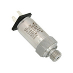
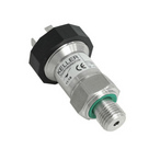
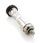
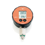
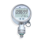
Thanks to piezoresistive pressure sensors, digital manometers, recorders, and software solutions, we offer the necessary tools for accurate pressure measurement in closed systems, as well as for recording and analyzing pressure spikes.
KELLER sensors provide precise data and feature long-term stability, making them ideal for reliable system monitoring and pressure spike detection. Software solutions, such as data analysis, are also important for planning preventive measures and system optimization.
Pressure recording
A piezoresistive pressure sensor measures the dynamics of pressure changes, including pressure spikes. Standard KELLER pressure sensors with a cutoff frequency > 1 kHz provide the basis for detecting rapid pressure spikes. The standard configuration of Y-Line is 1 kHz, X-Line for three-wire voltage output - > 1 kHz. For even faster measurements, the 21PHB model is available with a frequency of 20 kHz.
Data display
Digital sensors display real-time values and store the maximum displayed value.
Analysis and optimization
Software analyzes data to identify pressure spikes and develop countermeasures.
For more information about the instruments, you can contact IZMERKON by phone at +7 (812) 309 56 05 or via the feedback form.
_80x0_e6f.jpg "Pressure Transmitter Series 23SX-H2")
1)_80x0_e6f.jpg "Happy Defender of the Fatherland Day!")
_80x0_c25.jpeg "Radar Level Meter IZMERKON RL 37")